All modern Nikon DSLR cameras (starting with the D40) have an infrared (IR) receiver which is used to remotely activate the shutter and take a photo. Modern cameras can also be programed when connected to a computer via USB. There are several apps to control the camera with the computer or with a smartphone or tablet. However, this still remains a wired connection and a computer is needed.
Nikon's remote control is the ML-L3 which uses a single button to send the signal to the camera to take a photo. This is done using an infrared LED which transmits a specific sequence with a specific frequency. So the same sequence can be implemented using a LED driven by a microcontroller. In this case an Arduino is used.
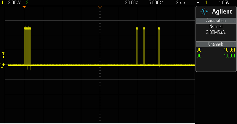
The sequence that needs to be transmitted is shown in the following figure which shows an oscilloscope display.
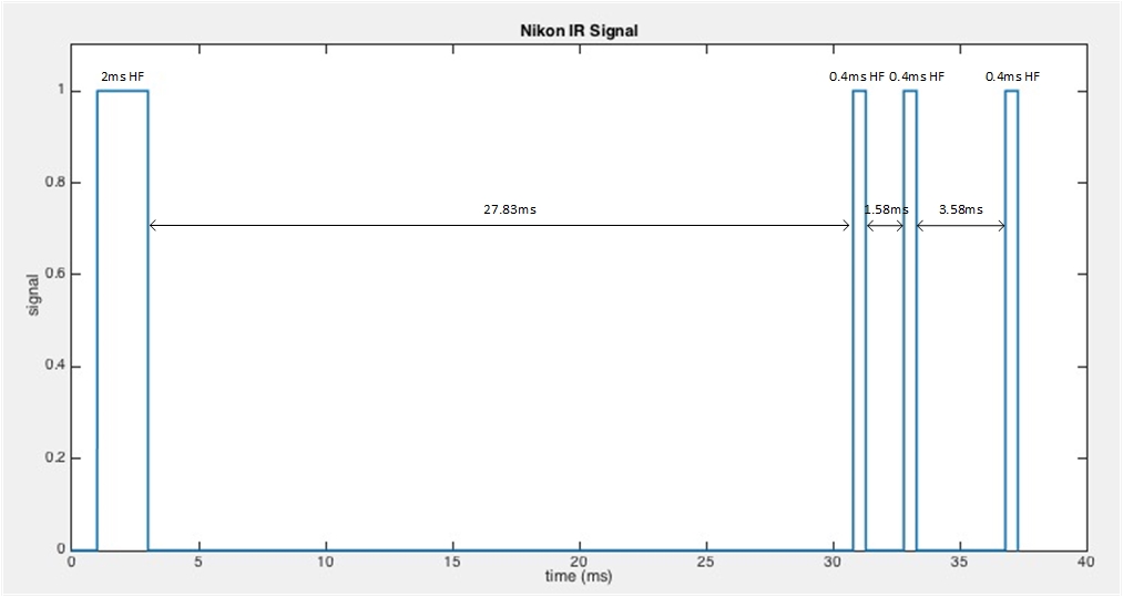
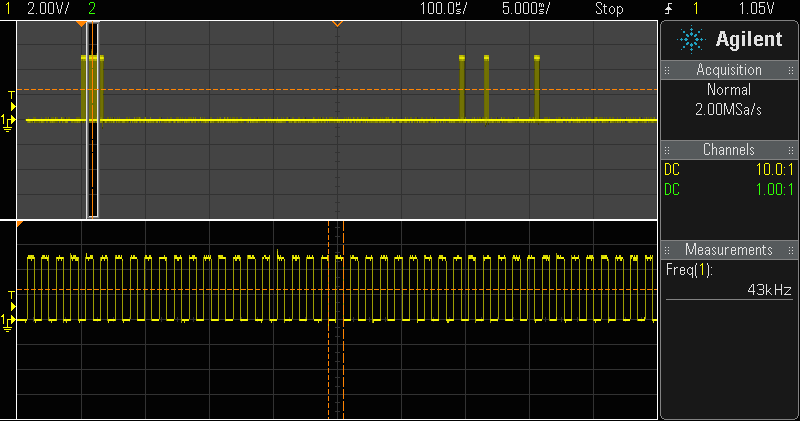
The modulation frequency of the LED is 38.4kHz. The timing sequence is shown in the figure below.
This timing sequence will be provided by the Arduino. An infrared LED needs to be connected to a digital pin, in series with a resistor (typical value 330Ω). The typical wavelength of an IR LED is 1050nm.
The code provided contains the function takePhoto(), which executes the timing diagram. Since the timing delays need to be rather accurate for the camera to respond, the CPU cycles for the rest of the operations except the delayus() need to be accounted as well, therefore the produced code has different timing sequence than the one shown above, so as to compensate for those cycles. The modulation frequency is a bit higher but it does the trick on the Arduino Uno.
The arduino sketch is also available as a Codebender project.
In the beginning of the program, you need to define the Digital Pin which is connected to the LED.
#define LEDpin 6
The function which operates the LED is called takePhoto().
void takePhoto(void) {
int i;
for (i = 0; i < 76; i++) {
digitalWrite(LEDpin, HIGH);
delayMicroseconds(7);
digitalWrite(LEDpin, LOW);
delayMicroseconds(7);
}
delay(27);
delayMicroseconds(810);
for (i = 0; i < 16; i++) {
digitalWrite(LEDpin, HIGH);
delayMicroseconds(7);
digitalWrite(LEDpin, LOW);
delayMicroseconds(7);
}
delayMicroseconds(1540);
for (i = 0; i < 16; i++) {
digitalWrite(LEDpin, HIGH);
delayMicroseconds(7);
digitalWrite(LEDpin, LOW);
delayMicroseconds(7);
}
delayMicroseconds(3545);
for (i = 0; i < 16; i++) {
digitalWrite(LEDpin, HIGH);
delayMicroseconds(7);
digitalWrite(LEDpin, LOW);
delayMicroseconds(7);
}
}
Finally, this sample program takes a photo everytime a button, connected to DigitalPin 0, is pressed. A pull-up resistor is used for the button. Happy snapping!
#define LEDpin 6
#define buttongpin 0
void setup() {
pinMode(LEDpin, OUTPUT); //led
pinMode(Buttonpin, INPUT); // button
}
void loop() {
if (digitalRead(buttonpin)==1) {
takephoto();
delay(1000);
}
}
void takePhoto(void) {
int i;
for (i = 0; i < 76; i++) {
digitalWrite(LEDpin, HIGH);
delayMicroseconds(7);
digitalWrite(LEDpin, LOW);
delayMicroseconds(7);
}
delay(27);
delayMicroseconds(810);
for (i = 0; i < 16; i++) {
digitalWrite(LEDpin, HIGH);
delayMicroseconds(7);
digitalWrite(LEDpin, LOW);
delayMicroseconds(7);
}
delayMicroseconds(1540);
for (i = 0; i < 16; i++) {
digitalWrite(LEDpin, HIGH);
delayMicroseconds(7);
digitalWrite(LEDpin, LOW);
delayMicroseconds(7);
}
delayMicroseconds(3545);
for (i = 0; i < 16; i++) {
digitalWrite(LEDpin, HIGH);
delayMicroseconds(7);
digitalWrite(LEDpin, LOW);
delayMicroseconds(7);
}