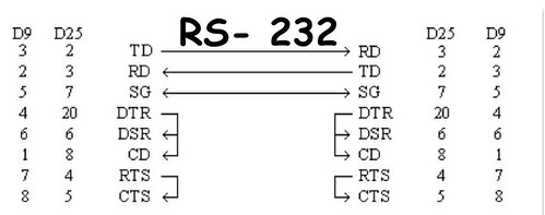
As part of a school project we had to connect two computers using an optical connection. In order to do so, we used a white LED and a photoresistor for the optical channel and the RS-232 port two transmit the data from the computer. The RS-232 was programmed in the asynchronus mode, with handshake so only one cable needed to be converted from an electrical signal to optical (TD->RD).
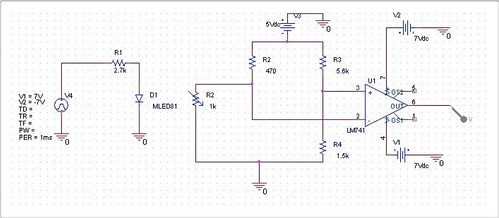
The designed circuit is very simple. In the transmitter the LED is directly connected to the TD cable (with a resistor in series). In the receiver, there are two voltage dividers, one to supply a variable voltage to the operational amplifier (pin 2) and one to supply a constant voltage (pin 3). After that the opamp compares the two voltages and outputs either -7V(when light is received in the photoresistor) or +7V(when there is no light).
The transmitter and the receiver were programmed in C, but any programming language can be used to communicate with the RS-232 UART.
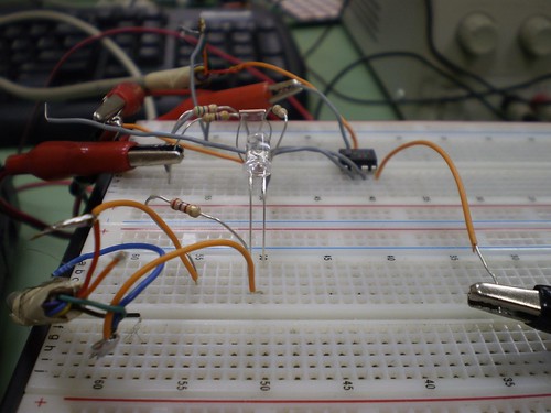
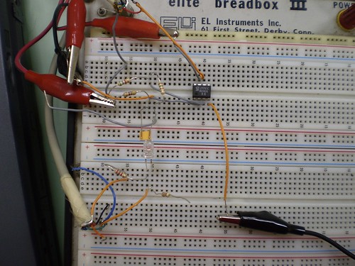
The final circuit can be seen in the following photos, as well two videos of its operation.