A project I have been working on for the past several months is the design and development of a quadcopter, using a custom control board powered by an STM32 microcontroller.
The Hardware
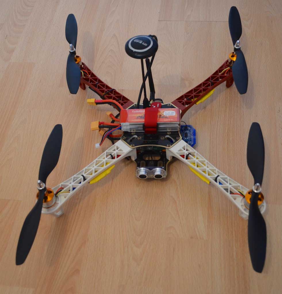
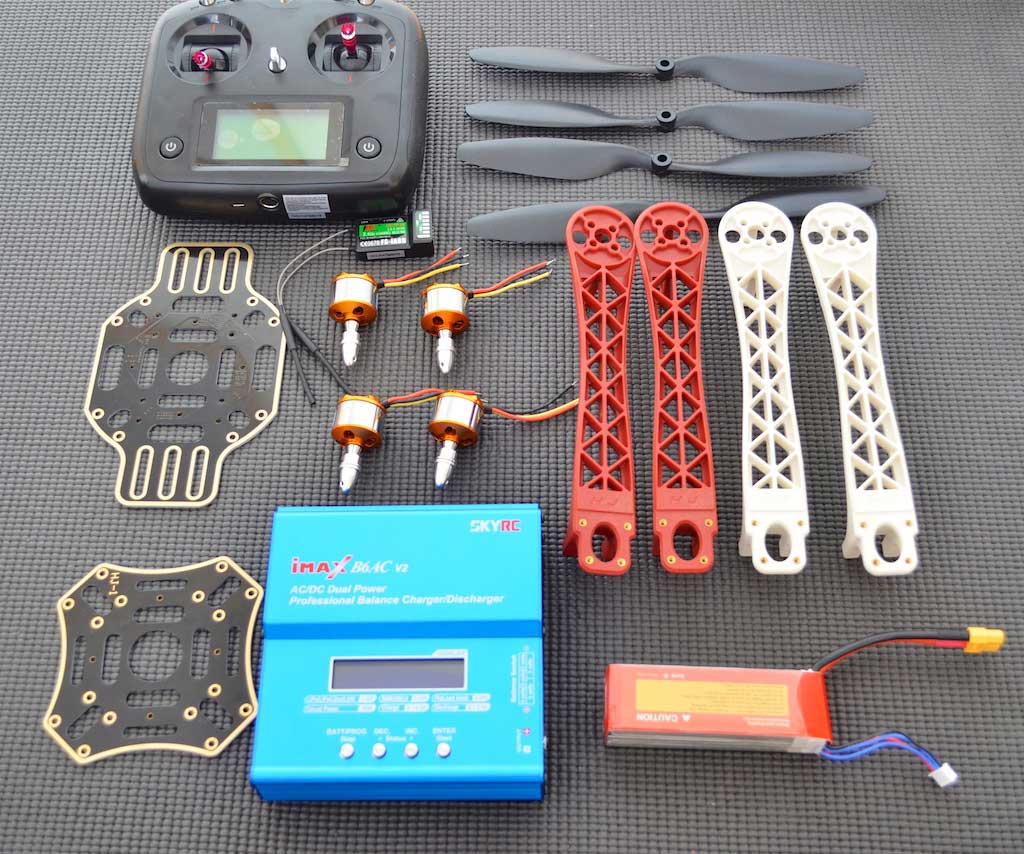
1) Quadcopter components
Other than the controller board, the rest of the components were stock parts, the majority of which were inspired by a similar project found in brokking.net. More specifically,
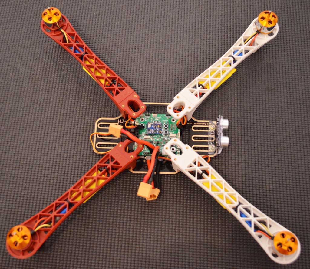
- The quadcopter frame is a basic HJ 450 frame
- The motors and ESCs were purchased together. They pack contained two 1045 propellers (depending if the rotor would spin clockwise or counter clockwise). Each ESC has a theoretical current of 30A and can be powered by a 2-4 cell battery. I also provides a 5V regulator. Although it will not be the primary controller supply, it will be used as a contingency one.
- The R/C transeiver is the 6-channel Flysky 2.4GHz combo. Although the transmitter supports 10 channels, I opted for the 6 channel receiver, since I don't need more channels and it has a smaller footprint.
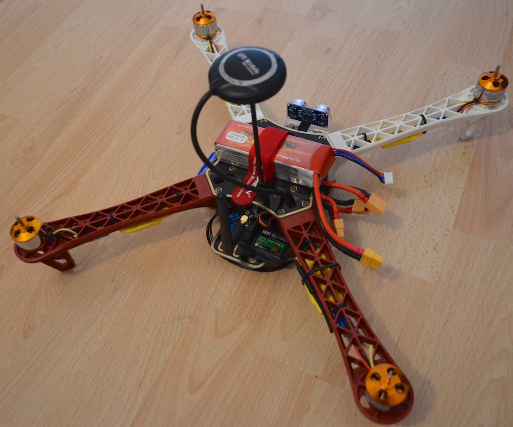
- The battery is a Floureon 2.2Ah 3-cell LiPo
- The battery charger is an iMAX battery charger which can be used with a DC power supply as well as by connecting it directly to the mains. It has charing and discharging functionality (with selectable charging current), as well as balancing and supports up to 6-cell batteries. I also used a battery pouch for safely storing the battery.
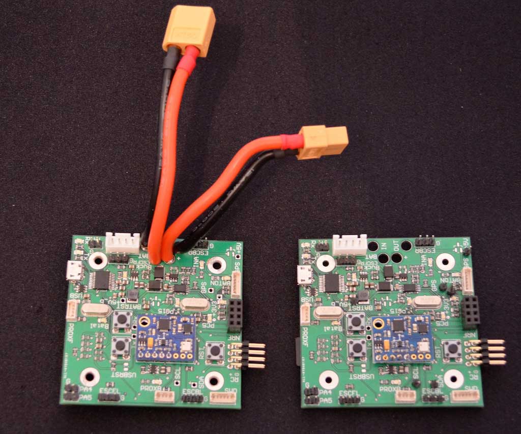
- I used a 12AWG wire for connecting the battery to the controller board (for voltage and current measurement) and for the distribution board.
- I used the XT60 connectors from the battery to the control board and to the distribution board.
- Banana plugs were connected between each ESC and each motor as well as between the distribution board and the ESCs. This is to ease repairability as well as to quickly swap the motor phases for changing the spinning rotation.
 |
 |
2) The control board
The requirements I wanted for the control board were:
- IMU (inertial measurement unit) based on an accelerometer, gyroscope and magnetometer. It would also get inputs from a GPS module and a barometer
- Control of the ESCs via PWM
- Power input either from the quadcopter battery or a micro-usb port
- Input from two proximity sensors (one mounted on the front and one mounted on the bottom) for autonomous flying
- Input from a 6-channel R/C receiver
- Battery monitor (current and voltage) and battery balancing support
- Wired and wireless of telemetry data
- Diagnostics for auxiliary voltage supplies and current consumption
- USB support for telemetry and debugging
- EEPROM for saving calibration values
- SD card support for data logging
- Low power consumption
Ok, the last requirement is a bit of an overkill, since the motors will drain the batteries rather quickly, but it's just for extra challenge when designing the power circuit. The main components of the controller board together with the external interfaces are:
- An STM32L4A6 low-power 32-bit micro as the heart of the controller board. I could go with a much less capable microcontroller, however I want to use this board as a development platform for other stuff as well.
- A U-blox Neo-7M GPS module, capable of communicating via UART and I2C.
- Two HC-SR04 ultrasonic modules to be used as proximity sensors. They are triggered with a short pulse and return a pulse, the width of which is proportionate to the distance
- A 10DOF (degrees of freedom) IMU, comprising of an accelerometer/gyroscope (MPU-6050), a magnetometer (HMC5883L) and a barometer/thermometer (BMP180). It communicates via I2C.
- An NRF24L01+wireless transceiver operating at 2.4GHz. It communicates via SPI.
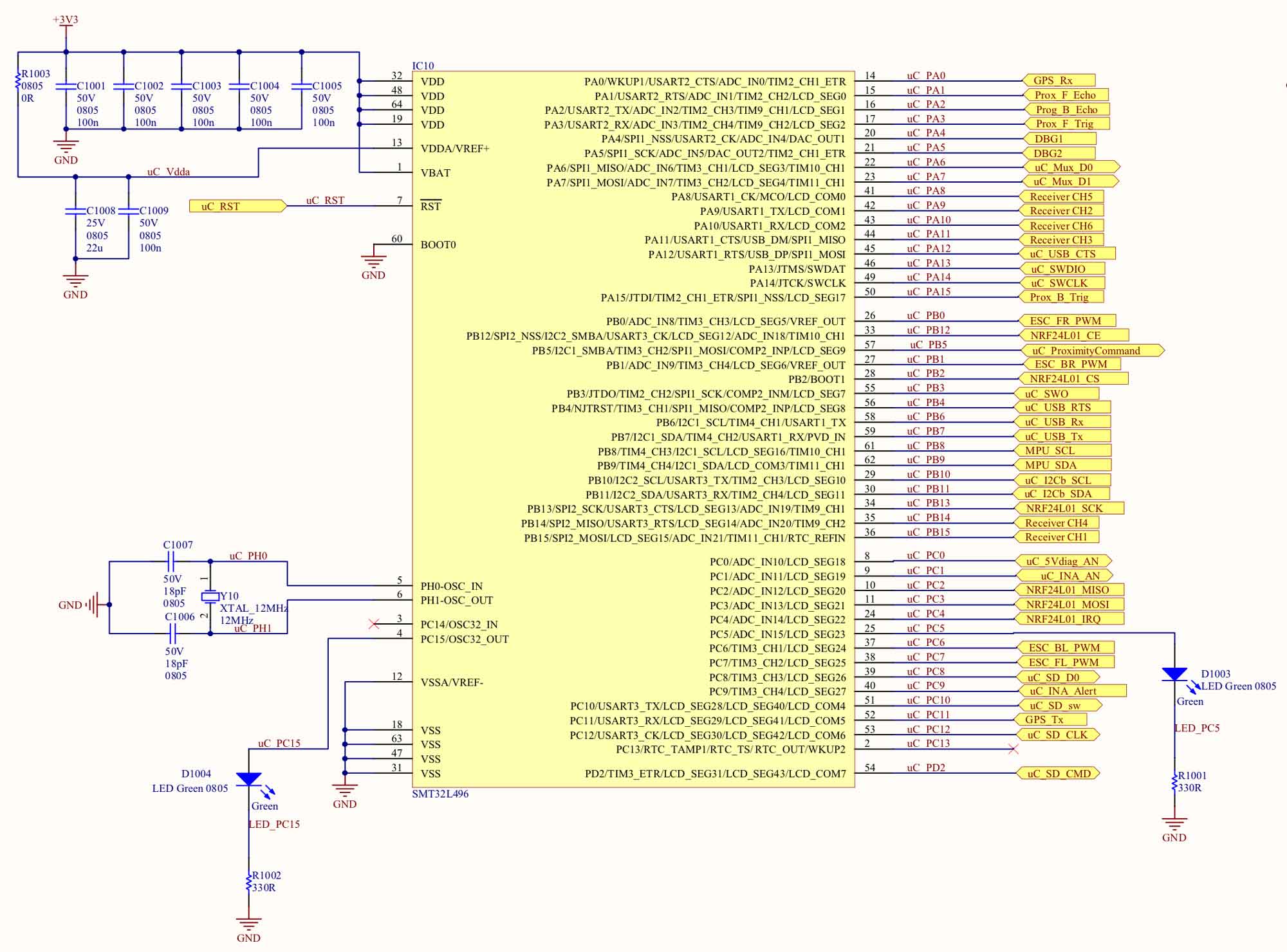
The full schematic can be downloaded as a PDF. It contains each function in a different sheet, as well as the design notes and the component values used. In the following paragraphs, the main functions will be detailed.
Power Supply architecture
The power to the board can be supplied either from the on-board Li-Po battery while flying, or from the USB connector during development.
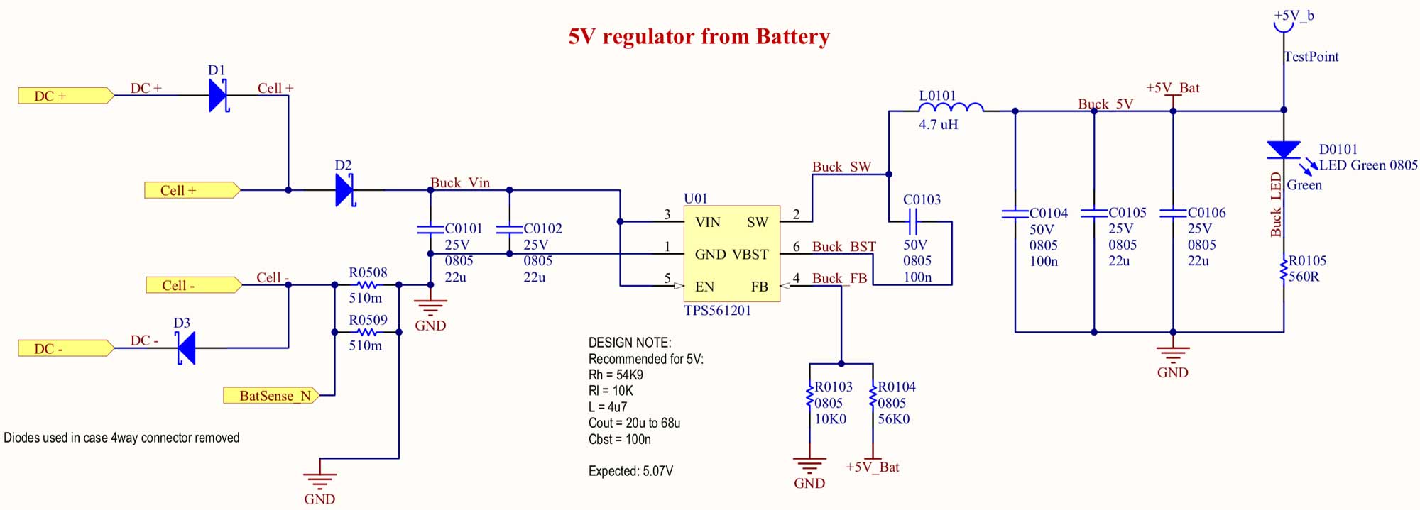
The power from the on-board battery is supplied using a high efficiency Buck converter (TI TPS561201) outputting 5V. The IC has the MOSFET and the diode of the converter integrated, together with the PWM controller and needs externally the inductor as well as the smoothing capacitors. The output voltage is fixed using a resistive divider feedback. It has an internal over-current and under-voltage protection. Normally, the voltage will be supplied by the balancing connector, since the controller might need to be operating before connecting the power to the ESCs and the motors. However, in case of disconnection, the power can be supplied by the main battery connector. Schottky diodes are connected to enable the use of this connector as well. Moreover, in case the whole 5V supply architecture fails, schottky diodes are also used to get the power from the ESC regulators. Since the specific ESCs have linear regulators, they can be used in parallel.
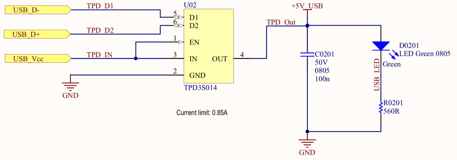
The power from the USB port (already at 5V) can also be used. It passes through a USB switch (TI TPD3S014) which is used to provide current limit protection as well as ESD protection for the USB peripherals.
Both supplies are fed to a power supply multiplexer (TI TPS2115A) which combines the two. In case one of the two supplies is present, it is fed through. In case both are present, the USB supply is fed through, however, the microcontroller can enable the use of the battery supply instead. The multiplexer also provides current limit protection.
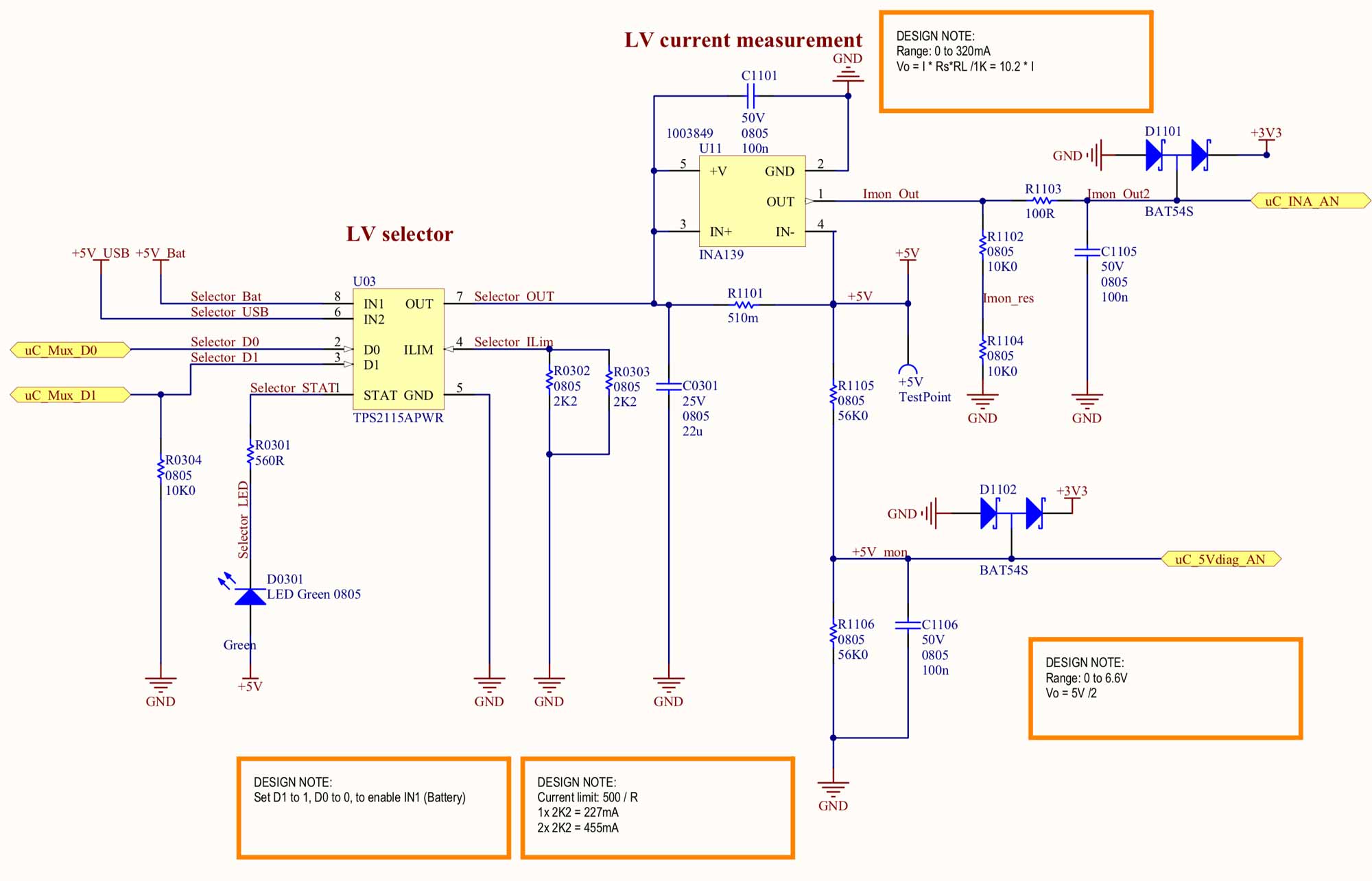
The 3.3V rail is supplied through a linear regulator (TI TPS732) which also provides over-current protection.
The output of the multiplexer is passed through a current supply monitor (TI INA139) which samples the current through a shunt resistor and provides the voltage to the microcontroller analog pin. The 5V rail is also sampled from the microcontroller through a resistive divider. The microcontroller contains an internal reference, so the 3.3V supply rail is compared to this reference, in order to determine the value of the 3.3V rail as well.
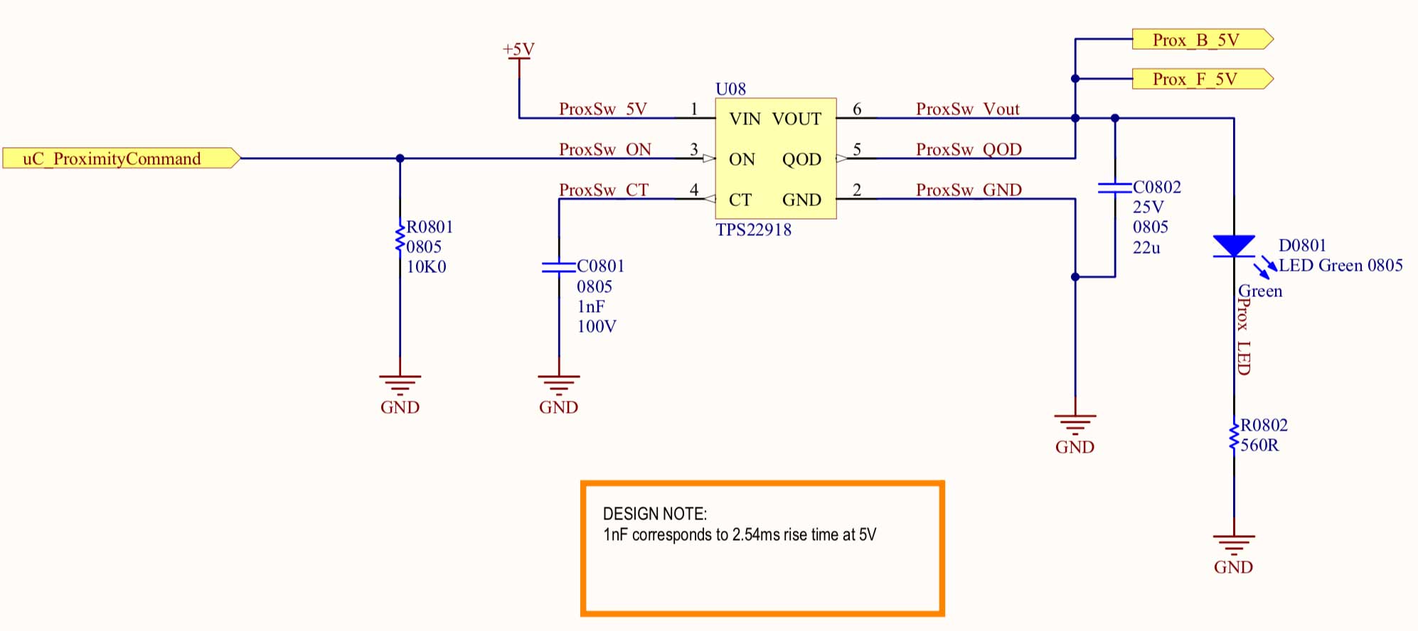
For the proximity sensor supply, which draw high current even at standby, a load switch (TI TPS22918) is used to cut the supply when they are not used. It also provides adjustable voltage rise time, in order to avoid inrush currents.
USB communication
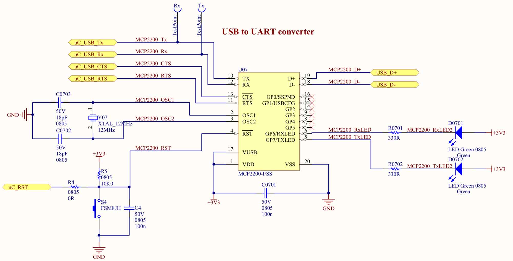
Although the microcontroller supports USB communication, I opted for a USB to UART converter (Microchip MCP2200) between the microcontroller and the USB port. This way I wouldn't need to have fixed impedance tracks on the board, since the IC will be placed very close to the USB port. Moreover, for debugging, I can also sniff the internal UART communication. The hardware flow control pins were also used, even if the throughput is not expected to reach the limits of the micro or the converter. LEDs were used to show if there is data transfer. The converter needs a reset line, so it can use the same Reset pin of the microcontroller, or can use a separate button. It needs an external crystal to operate.
Battery monitoring and balancing
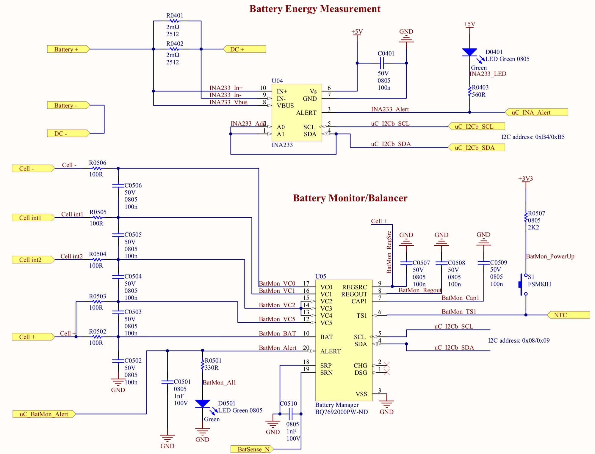
The role of this function is to provide monitoring of the battery via the telemetry as a whole and also a per cell. Because of the nature of the board, there won't be any protection that will cut-off the power (since this will cause the quadcopter to fall from the sky). An under-voltage shut down protection exists in the ESC, however, the alert threshold will be set to a much higher level. The main IC for the battery measurement is the TI INA233. It samples the battery voltage and current (via a shunt resistor) and communicates with the microcontroller via I2C. Moreover, it has an internal energy measurement (by integrating the power measurement), therefore it is easy to calculate the charge used on the battery. For the monitoring of each cell, the TI BQ7692000 is used (now not recommended for new designs). It samples the voltage of each cell and communicates via I2C as well. Moreover, it has a thermistor input to monitor the battery temperature. It also provides balancing functionality, which is supported on the board, although the battery charger will be mainly used for balancing the batteries. Finally, the current monitor channel is used to monitor the current fed to the controller board circuits. Both ICs have alert pins which are connected to the microcontroller for diagnostic purposes and not for actual hardware shut downs.
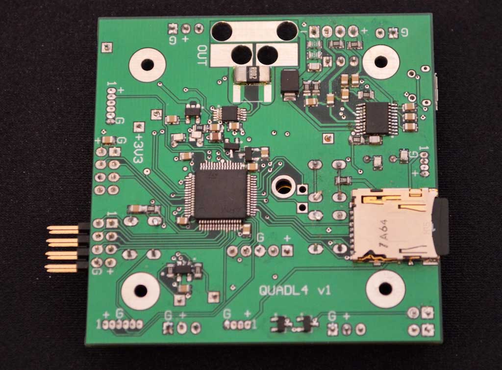
Microcontroller
The STM32L4A6 ARM Cortex M4 microcontroller is used. The specific part is a 64-pin LQFP, needed for the connection of all the peripherals. It supports SPI (for the connection with the wireless transceiver), I2C (two buses for the IMU, the battery monitor and the I2C EEPROM), UART (for the USB communication and the GPS module) and SDIO (for the micro-SD memory card for logger). Moreover, the timers that exist are used for input capture of the signals from the R/C receiver, the proximity sensor measurement as well as the command to the ESCs. An external crystal is used for accurate clock frequency (though not necessary for the specific application). The microcontroller is programmed through SWD, so a programming connector is also placed on the board. The specific micro has 1MB of flash memory and 320KB of RAM which again is an overkill, as well as the AES encryption that it supports.
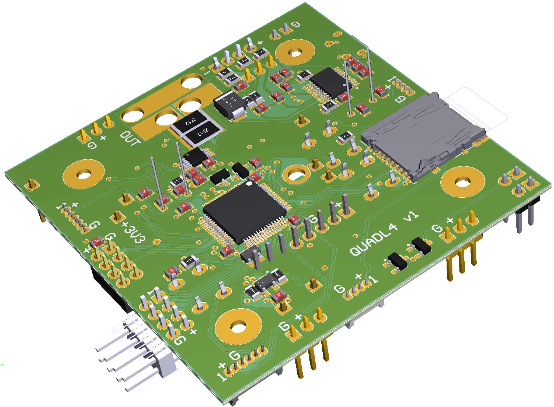
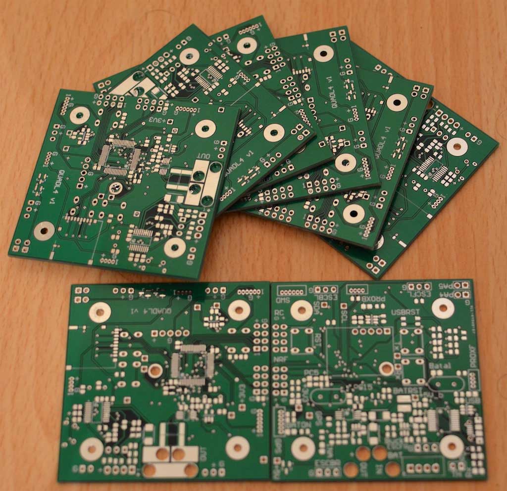
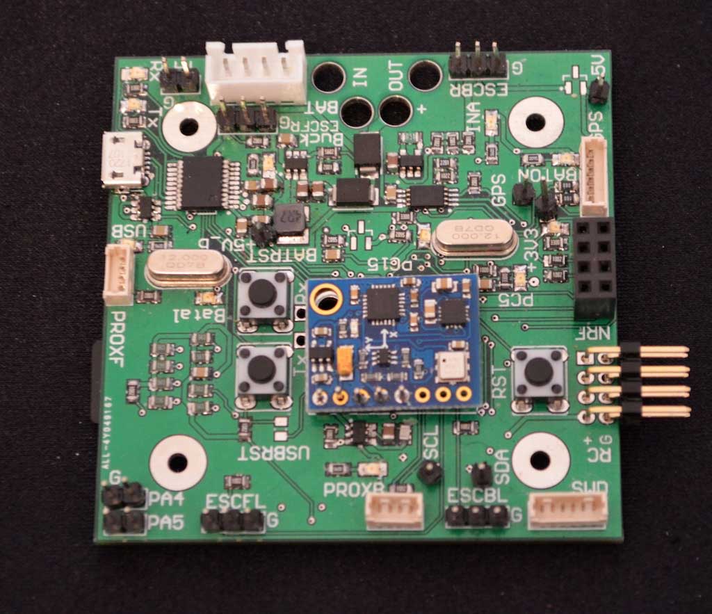
PCB and mechanical
The controller PCB is to be mounted between the two boards that form the frame of the quadcopter. Since the bottom PCB is the distribution board, spacers are used to elevate the controller PCB above that. In the same area, the proximity sensors, R/C receiver, and wireless transceiver are also placed. Therefore, the PCB is 6.5cm x 6.5cm and the component placement shows the density that is needed. Four layers were used to route all the signals and colleague helped with the routing, thanks Marko :)
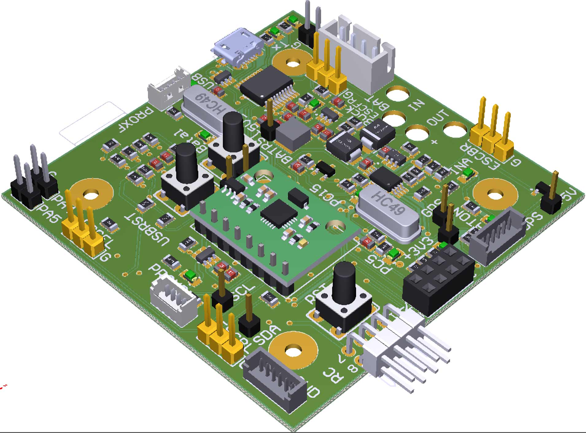
Soldering was quick since I used 0805 components. After finishing the board bring-up, it was mounted on the frame. The rest of the components (GPS, proximity sensors, R/C receiver, 2.4GHz transceiver) were also mounted. Moreover, a through-hole thermistor was mounted on the battery and routed to the PCB connector.
You can view all the hardware files on my github repository.
The Firmware
The firmware is based on interrupts for each different function.
Interrupts and priorities
Interrupt priorities ensure that there will be no deadlock because of timings. A watchdog timer is used to ensure that the microcontroller will reset in case of a fault.
The watchdog timer update is handled in the lowest interrupt function.
The input capture functions for the proximity sensors and the R/C receiver have the highest user interrupt priority, in order to ensure that the capture/compare register value for the rising edge is captured before the falling edge that would appear 1ms afterwards.
Then, the main loop interrupt has the highest priority. In this function, the microcontroller gets all the AHRS sensors measurements, calculates the Euler angles, applies the PI controller and determines the ESC speed. The I2C module is clocked at 400kHz, so this function needs 1.2ms maximum and has a 250Hz refresh rate.
The NRF24L01 EXTI interrupt priority follows (triggered every time that the NRF24L01 transmitter completes successfully a packet transmission or hasn't received an acknowledge after several tries), to load the next packet to send.
The UART interrupt for the GPS parser follows, triggered every time that the UART receiver detects an end of transmission (explained in detail below). The received string is parsed to determine the GPS values, which takes 6ms (every 1000ms).
The rest of the peripherals follow (USB communication interrupt, timer interrupt for acquisition of battery measurements, ADC interrupt for analog measurements, timer interrupt for wired and wireless telemetry, EXTI for SD card connection or battery alert), since those are not so time critical for the correct operation of the quadcopter.
UART receiver and DMA
The GPS receiver send a NMEA text string every second. The target was to use the least processing power to determine when the transmission has finished.
One way of doing this would be to use a timer: As soon as the first character would be received by the UART module, an Rx interrupt would start a timer, which would count enough to ensure that the whole message has been received (e.g. 200ms) and then, the processor would wait for the timer interrupt to parse the message. However, this means that the processor would be used twice and that a lag would occur, since there needs to be a safety margin for the timer.
Luckily, the STM32L4 UART peripheral has a "Receiver Timeout" (RTO) interrupt event, which triggers every time that a UART packet with multiple bytes stops (and is user configurable). Since the GPS sends the full NMEA message in one go, triggering on this interrupt is the way to go. A DMA transaction is implemented to get all the UART bytes and store them on a buffer. As soon as the interrupt is triggered, the GPS parser gets the data from the buffer and updates all the GPS related measurements.
Proximity power control
As explained in the hardware section, the proximity sensors draw significant current even at standby (though not as significant as the GPS module). A power switch was used to power up and down the two proximity sensors. To limit the peak current, the proximity sensors are triggered sequentially, first the front sensor and then the bottom sensor. So the sequence is:
- Power up the sensors
- Wait for some time (20ms) for the initialization
- Send a trigger to the front proximity sensor
- Receive the echo from the front sensor
- Send a trigger to the bottom proximity sensor
- Receive the echo from the bottom sensor
- Power down the sensors
The sequence is shown in the figures below.

(zoomed in)

As can be seen, the proximity measurement is triggered every 250ms after the previous measurement. The Vcc line (5V) switches on and waits for 20ms for initialization of the proximity modules. It then sends a short trigger pulse to the front sensor and immediately it returns the echo pulse, which is used to determine the proximity length. As soon as the falling edge of the echo pulse is captured from the microcontroller, it sends the second trigger pulse, to the bottom proximity sensor. As soon as the second sensor, returns its pulse, the microcontroller immediately cuts the supply, through the voltage switch.
Wireless transmission
The NRF24L01 handles all the low level communication between the transmitter and the receiver. The user needs to setup the modules (transmission speed, channel, power, number of bytes per wireless packet etc.) and send the commands and the data via SPI. Since each telemetry packet is 256Bytes long, the maximum 32Byte packet is selected. The procedure for the transmission of a telemetry packet is as follows:
- The first wireless packet is transmitted via SPI and then the CE (radio enable) signal is pulled high.
- The processor waits for an interrupt of a successful or unsuccessful transmission (depending on a reception of an acknowledge from the receiver).
- It then transmits the second wireless packet via SPI and waits again.
- This sequence is repeated for all the 32Byte packets.
- After the final packet, the processor turns off the radio, until the next transmission.
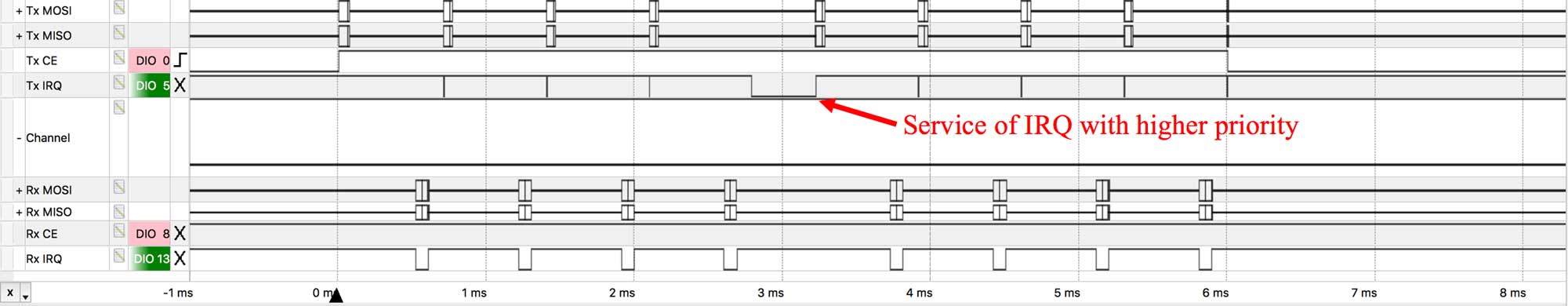
The sequence can be clearly seen in the figure below, where all the signals from the transmitter and the receiver are shown.
To explain the sequence, the individual SPI signals are collapsed, to simplify the waveform. As can be seen, a complete telemetry packet transmission needs about 6ms to transmit at 1Mbps, so the transmission rate can easily go above 100Hz, without needing to increase the bit rate to 2Mbps.
Zooming in further, a single telemetry packet consists of 8 individual 32Byte wireless packets, to form the 256Byte length. The transmitter sends each packet through SPI and waits for the interrupt by the NRF24L01+, to verify if the transmission was completed and send the following packet. As can be seen, the interrupt priority for this is lower than a more important microcontroller task (the AHRS algorithm for acquisition of the motion sensors and calculation of the Euler angles), therefore, there is a case where the IRQ is not serviced immediately. As soon as the first packet is loaded, the transmitter radio is enabled (CE high) and it is disabled after the final ACQ from the receiver (which is detected through the IRQ pin). On the other hand, the receiver radio is always enabled, to receive the packets. Different SPI frequencies are used for the transmitter and the receiver as can be clearly seen.
Going even further on the transmission of a single packet, it can be seen that the transmitter needs about 710us for each transmission. About 80us are needed for the loading of the buffer via the SPI bus. The NRF24L01+ datasheet states that the transmitter needs 130us to enter Tx mode from standby. Furthermore, the enhanced shocksburst packet format has a preamble segment (1Byte), an address segment (3Bytes), the payload (32Bytes) and a CRC segment (1Byte), making it 37Bytes in total. At 1Mbps, the packet transmission needs 296us. Adding the 130us setup delay, it needs theoretically 426us to transmit the packet. As shown below, the receiver needs 442us to pull low the IRQ pin, signaling that a new packet has been received. Considering that a short time is needed to compute the CRC and determine if the address corresponds to the specific receiver, the timings are validated.
NRF24L01 transactions:
![]()
NRF24L01 single telemetry packet:
NRF24L01 single wireless packet:
![]()
The Telemetry Software
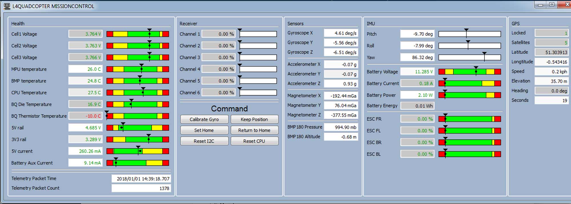
Apart from offline telemetry, which is saved in the SD card, wired or wireless real-time telemetry is achieved using USB communication or the NRF24L01+ respectively. All the important (or less important) measurements are packed and sent every 50ms. For the wireless telemetry, a second board is connected to the computer, which converts the NRF24L01 packets to USB packets. Synchronization and termination packets are used to ensure the robustness of the channel, which is also ensured by the CRC checks and the retransmission in case of NACKs.
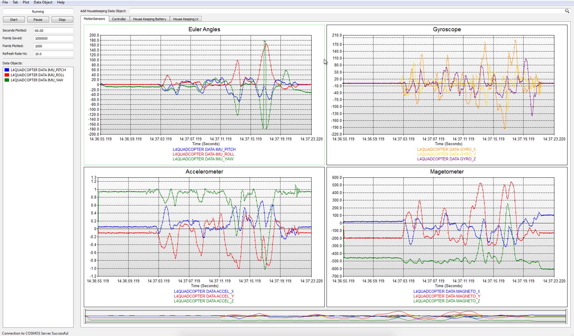
On the PC, the Bell Aerospace COSMOS software is used. Both channels (wired and wireless) are configured. A telemetry viewer screen is constructed to show all the measurement values as well as its limits. Through the same window, the user can send back some commands to the quadcopter. Furthermore, a telemetry grapher is also setup to see the measurement values over time.