1) Introduction
Traditional grid-connected photovoltaic (PV) systems consist of numerous solar panels, usually connected in series, which feed dc current to a centralized inverter, whose role is to supply this power to the ac utility grid. A different approach is to have a dedicated microinverter (with a nominal power range of 100W-300W) for each solar panel. The use of this technology guarantees maximum power generation under any weather condition or partial shadowing (since maximum power point tracking - MPPT is applied to each solar panel individually), while at the same time being reliable and easily upgradable.
Microinverters are installed on the back of the solar panel, either on the supporting rail or inside the junction box. Disadvantages of this approach is the higher initial cost of the installation, as well as the lower power efficiency that they achieve compared to string inverters, at least for the time being.
The converters can be either single or double stage. On double stage converters, the first converter is a dc-dc voltage step-up converter, which boosts the PV output voltage (25V-50V) to about 400V and performs MPPT. The second converter is an inverter which converts the high voltage dc to ac. On the other hand, the single stage approach embeds both functions on a single inverter, with the advantage of increased efficiency.
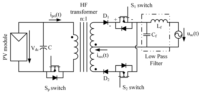
The Flyback inverter topology (shown in the figure below) is as a single-stage inverter which is widely used, due to its many advantages (high-voltage step-up ratio, electrical isolation, high power density, increased reliability, and low cost). My research focuses on increasing the weighted power efficiency of the microinverter by applying an improved control algorithm, by appropriately selecting the design parameters of the converter and by using state of the art wide bandgap devices. All of the above are based on the mathematical formulation of power losses of the converter as well as on computer simulations and experimental results of laboratory prototypes.
2) The Hybrid DBCM conduction mode
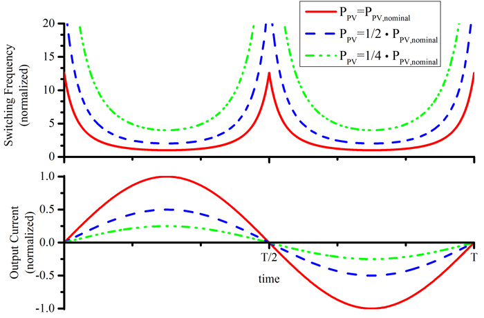
The two most widely used operating modes of the flyback inverter are the discontinuous conduction mode (DCM) and the boundary conduction mode (BCM). In both modes, the converter operates as a current source, rendering the control scheme fairly simple. In DCM, the switching frequency is constant and the flyback transformer is fully demagnetized before the next switching cycle, whereas in BCM, the transformer is momentarily demagnetized, leading to a variable switching frequency. Comparing the two principal operating modes, DCM requires the least amount of hardware; however, its power density is limited. On the other hand, although BCM is fairly more complicated, it can be implemented with or without high frequency sensors and can provide increased power density, since the transformer is continuously utilized. Nevertheless, its power efficiency is limited at lower PV irradiance levels, due to the increased switching frequency of the main transistor. As an example, in the following figures, the switching frequency of a converter operating in BCM is presented, for different irradiance levels. Notice that at the edges of the sinusoidal wave, the switching frequency is elevated, increasing the switching losses. What is more, as the solar irradiance decreases, the overall switching frequency is increased.
 | 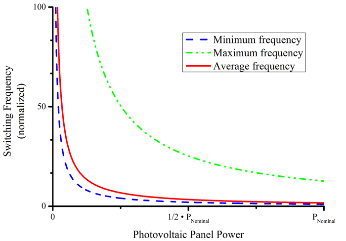 |
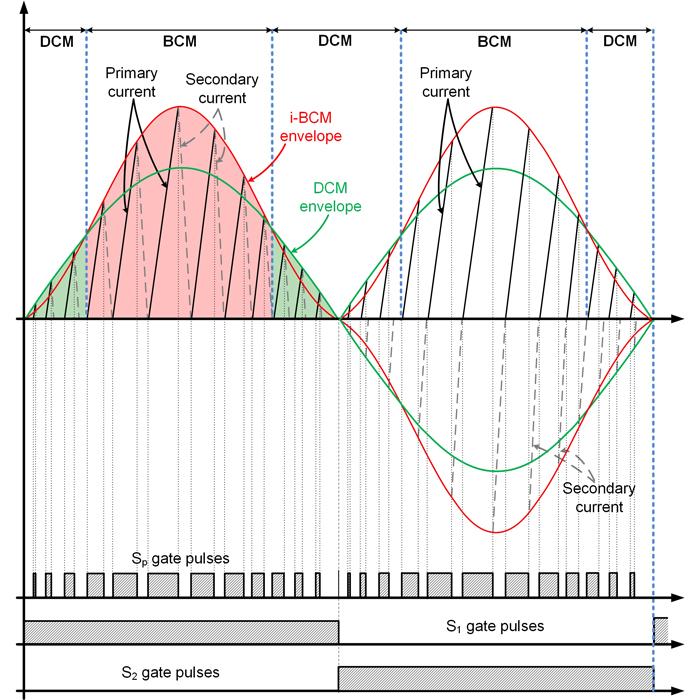
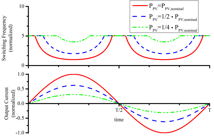
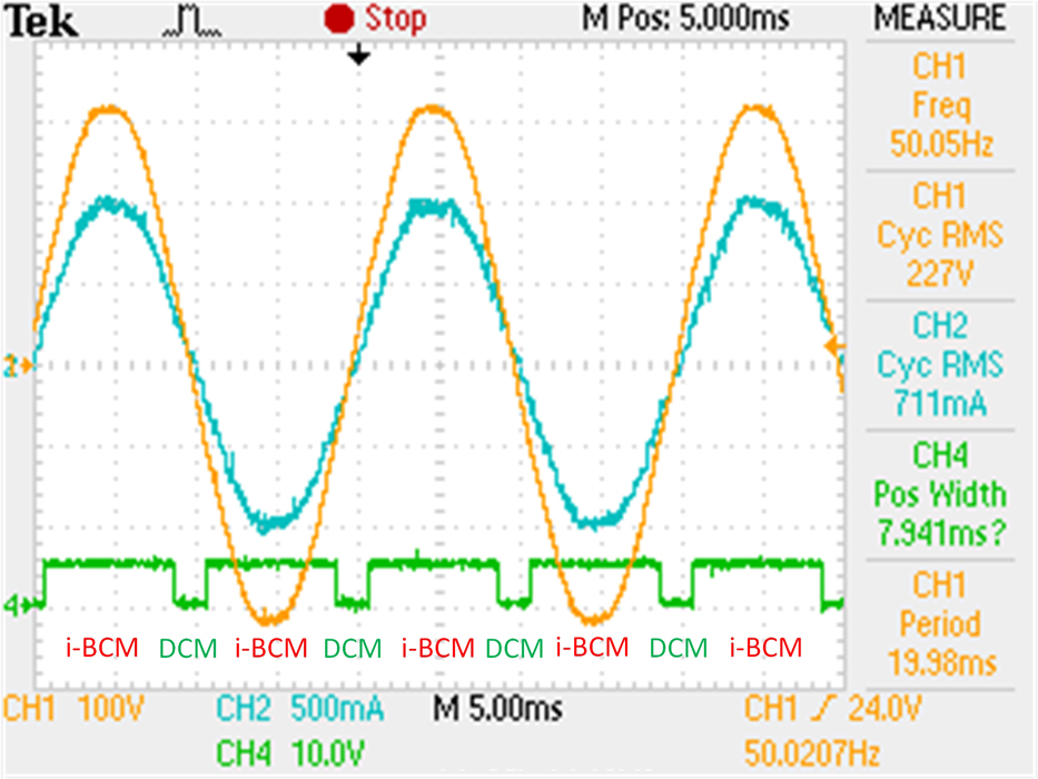
As a solution to the problems mentioned above, the hybrid DBCM switching mode was proposed. The converter operates in both DCM and BCM during the utility grid half cycle for high PV power levels, whereas it operates only in DCM under a critical PV power level. So, during a grid half cycle the DCM and BCM modes may coexist. The switching sequence of each semiconductor for this hybrid operating mode is presented in the figure below. As it is shown, the converter operates in BCM near the center of the sinusoidal wave, where the instantaneous output power is high, whereas near the edges it operates in DCM, with a constant switching frequency. As the power level decreases, the DCM operation percentage increases and if the PV power is lower than the critical power level, then the converter operates fully in DCM. The switching frequency of the proposed hybrid mode is shown in below for different PV power levels.
The correct modulation parameters were calculated based on derived mathematical expressions, in order to have a pure sinusoidal output current, which is mandatory for modern PV inverters. Simulation results depicted below show the principal current waveforms during the hybrid conduction mode operation.
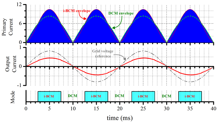 | 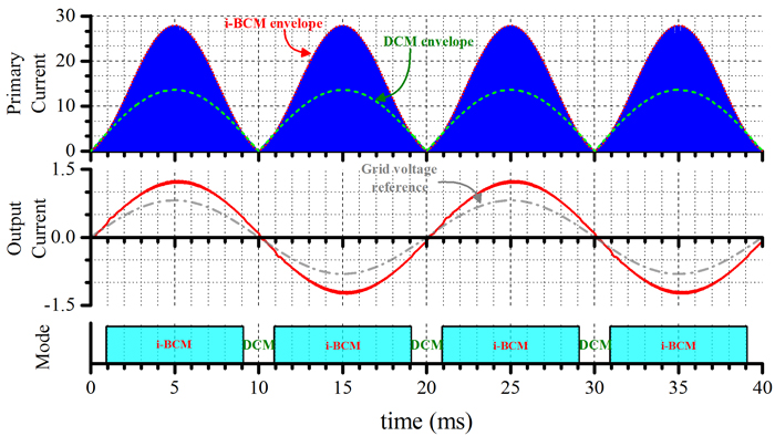 |
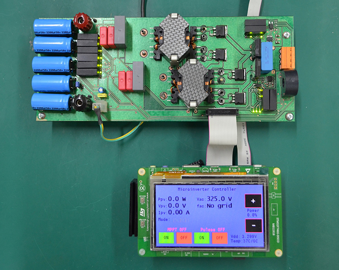
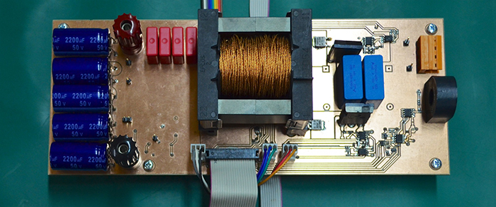
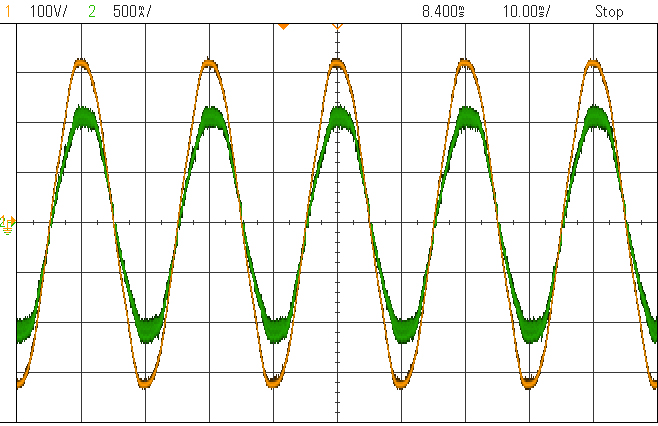
A laboratory experimental prototype was designed in order to validate the mathematical analysis and to quantify the improved efficiency results because of the proposed control algorithm. The following figures show the converter operation under various power levels. As the input power increases, the BCM percentage during the sinusoidal wave increases as well.
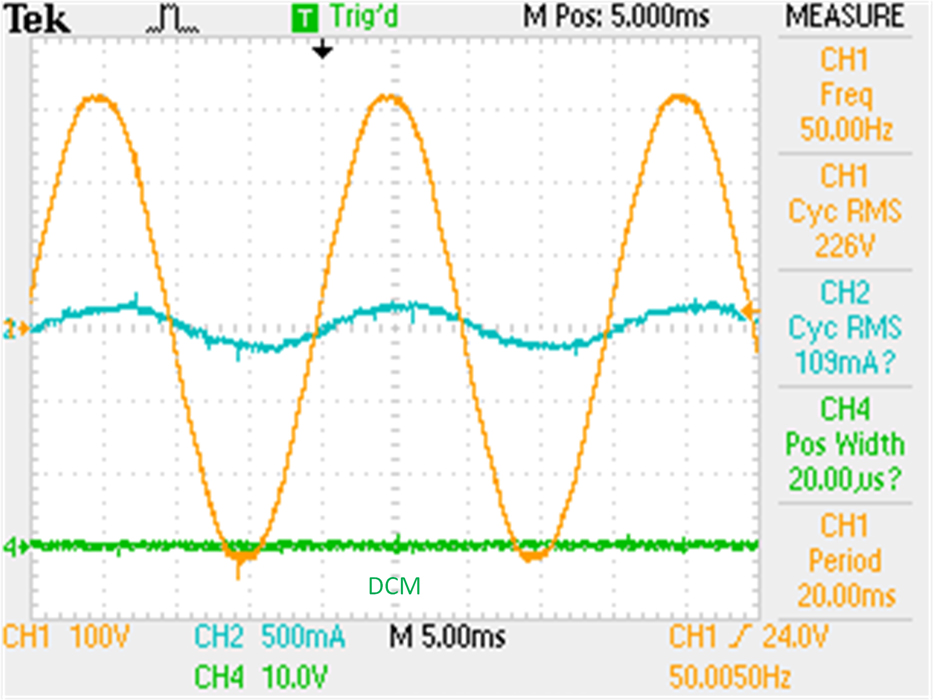 | 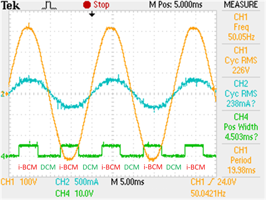 |
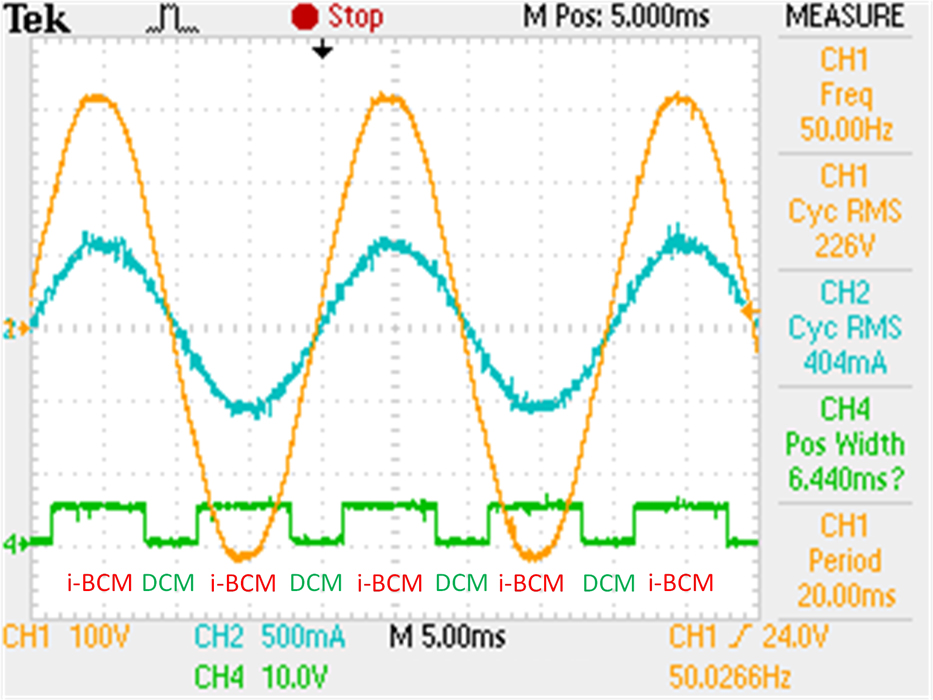 |  |
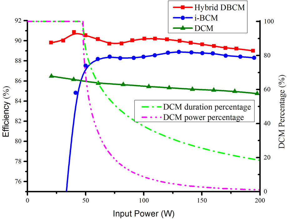
The efficiency of thee converters with identical specifications operating in DCM, BCM and the hybrid DBCM is shown in the following figure. The efficiency using the proposed modulation is always higher than the one using BCM. This is especially true in the lower power levels where the improvement is more significant. This is due to the fact that in those lower power levels, the percentage of DCM operation is higher and so the maximum switching frequency is limited. This leads to a higher converter efficiency for a wider power range. Moreover, the efficiency gain is more notable for higher input voltages, as the power percentage of DCM increases when the input voltage is increased. What is more, comparing the converter operating in the proposed hybrid mode with an equivalent converter operating in DCM, it is evident that the measured power efficiency is significantly higher for every power level and input voltage.
3) Hybrid DBCM design optimization
Having validated the improved performance of the hybrid DBCM operation, an optimization algorithm to appropriately select the design parameters of the converter (i.e. transformer turns ratio and inductance, DCM switching frequency, MOSFET breakdown voltage for the hybrid DBCM operation), in order to achieve the maximum overall efficiency.
To arrive at this optimization algorithm, the power losses of each component have to be described first. The following power losses were mathematically derived for the hybrid DBCM operation:
- MOSFET conduction loses: the rms current of each MOSFET was calculated in order to derive the conduction loss of each component.
- Diode conduction losses: the average current of each diode was calculated using the same sequence.
- MOSFET switching losses: the losses were calculated by calculating the energy lost during each switching cycle at switch-off (switch-on is under zero current because of the hybrid DBCM operation).
- Transformer core losses: the improved generalized Steinmetz equation (i-GSE) was used and the power losses were derived by calculating the energy lost during each switching cycle.
- Transformer winging losses: the ohmic losses for a litz wire are calculated, taking into consideration the increased ohmic resistance due to the skin and proximity effect, by deriveing separate equations for the dc and ac counterparts.
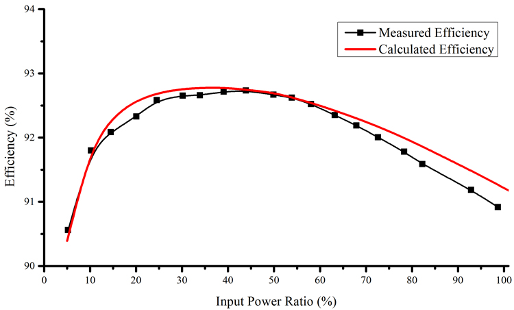
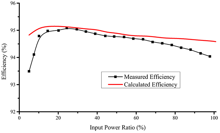
The power loss formulas of the flyback inverter operating in hybrid DBCM, together with the design constraints (transformer flux density saturation limit, maximum breakdown voltage of the switches, maximum transformer fill factor) were input in a software platform and the differential evolution stochastic method for constrained nonlinear global optimization is used to determine the optimal component values. To verify the optimization process as well as the power loss analysis, a laboratory experimental prototype was built, with the component values selected by the algorithm. In the figure below, the inverter output current at maximum power is shown. Efficiency measurements in order to determine the weighted efficiency of the prototype as well as to validate the power loss analysis for the hybrid DBCM modulation. The measured efficiency as a function of the input power compared to the calculated one, based on the power loss analysis, is shown below.
4) Interleaved converters
The proposed hybrid modulation has increased the converter perrmormance. The power loss analysis enabled the application of an optimization algorithm in order to appropriately select all the design parameters to achieve an improved efficiency. The application of this algorithm reveals the limitations of the current technology (compared to string inverters). In order to overcome those limitations, an interleaved topology is used, meaning two converters connected in parallel. However, depending on the input power level, both converters are not always active. Furthermore, the hybrid modulation is applied for each one, depending on the input power. The operation percentage of each converter as well as its operating mode (DCM or BCM) is modeled in the optimization algorithm, in order to appropriately select the design and operating parameters to achieve maximum weighted efficiency.
 |  |
 |
 |
5) Beyond: Active clamp
So, what’s next? The hybrid DBCM operation shows improved efficiency and the experimental results of the optimization algorithm prove that it can accurately predict the microinverter performance. The interleaved converter has bumped the experimental weighted efficiency to over 94.5%. Another important factor for the converter operation is the power loss due to the transformer leakage inductance. So, an active snubber will be used in the next prototype, the operation of which will be determined by the optimization algorithm as well.