Pedalboards are essential to guitar and bass players in order to change on the fly the sound of their instruments (volume, reverb, distortion, equalizer) or perform other actions (i.e. tuner, mute). Purists prefer to use analog effects (built with resistors, capacitors, opamps etc.), however digital counterparts are more advanced and less expensive on the long term. Most advanced pedalboards come with the effects built-in (digital effects with a powerful a/d and d/a converter) and sound banks. Since however computers have more than powerful processors (though they lack at a/d converter horsepower), there are many applications that emulate those effects. Moreover, computers come with other benefits for the bass player such as audio loops or sheet music. On the other hand, operating a keyboard or a mouse while playing the bass guitar is not the easiest thing in the world.
Given that large power amps also have an input for their own pedal board, it starts to get complicated. For example, Ampeg power amps have a two switch input to enable mute and their graphic equalizer. I use GuitarRig from Native Instruments on the mac, so I decided to build a custom pedalboard which would be used to control the amp, GuitarRig as well as any other app on the mac (i.e. GuitarPro which has tablature sheets).
The Hardware
First things first. The connections. The Ampeg amp connects to the pedalboard with a stereo 1/4" plug, whereas the mac needs a USB port. Furthermore, the pedalboard needs to provide feedback that a switch is pressed (via LEDs). A third LED is needed to show that the board is connected to the computer. Two footswitches are needed to operate the amp (mute and graphic equalizer). Another eight are added to operate the computer, as well as an analog pedal. So to sum up:
- 1/4" stereo plug for connection with the Ampeg amp
- USB connection with the computer
- 2 toggle foot switches for the amp
- 2 LEDs for the amp
- 8 foot switches for the computer
- 1 analog foot pedal
- 1 LED for power-on
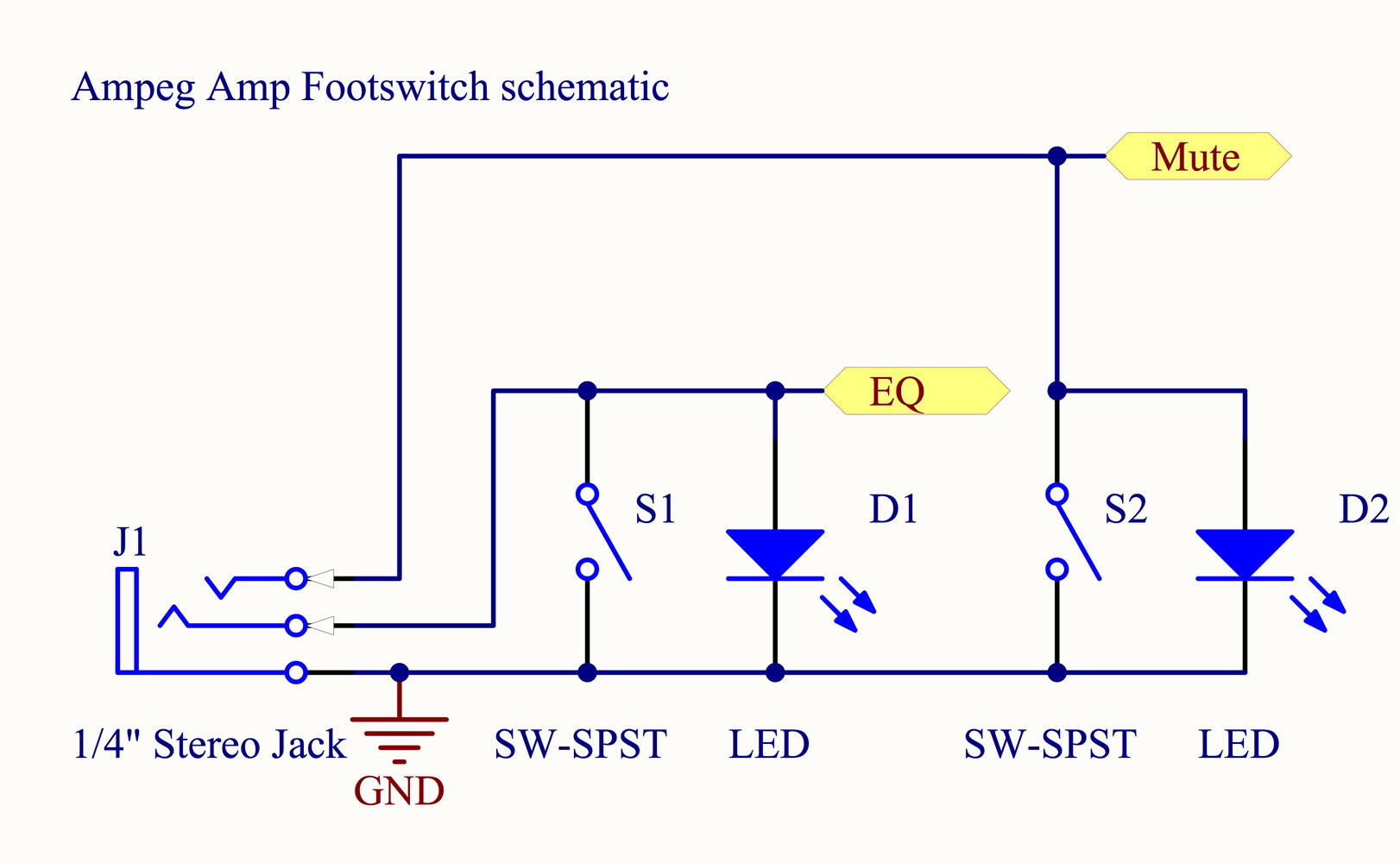
Let's start with the power amp footswitch part, which is the simplest. The circuit needed is fairly simple, as all the complex electronics are inside the amps (circuit schematics of Ampeg amps are available online). The 1/4" stereo plug has two signals, one for mute switch (tip) and for the EQ switch (ring) and a ground return (sleeve). Each time the signal is short circuited to the ground, 10mA pass through the short circuit and the equivalent button on the amp is considered as not pressed. If the signal is left floating then the equivalent button is pressed. In other words, the moment you plug any stereo plug on the pedal input of the amp, both LEDs on the power amp will switch on.
So for each signal, as switch is needed to short circuit it to the ground. Since the amp can provide the current, an LED can be added in parallel with the switch. So if the switch is not pressed, the LED with switch on. A resistor can be added in series with the switch to LED its brightness, but it is not necessary. The circuit needed is shown in detail in the following schematic.
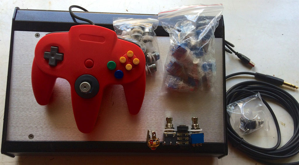
Now for the more complex part. To operate a MIDI device (needed to talk to GuitarRig or other music apps), you need a USB to MIDI interface. Thankfully, there are apps who translate Human Interface Devices (HID) to MIDI. Still, to build a USB HID, a microcontroller is needed together with a USB PHY. But, since all that is needed are buttons and analog pedals (or sticks), it is easy to transform an existing HID, to a footswitch, in this case, a $7 gamepad. All in all, these are the devices which will be used.
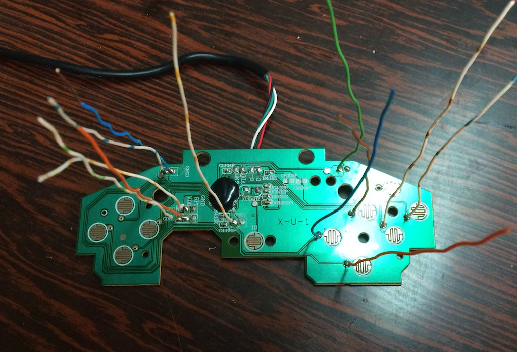
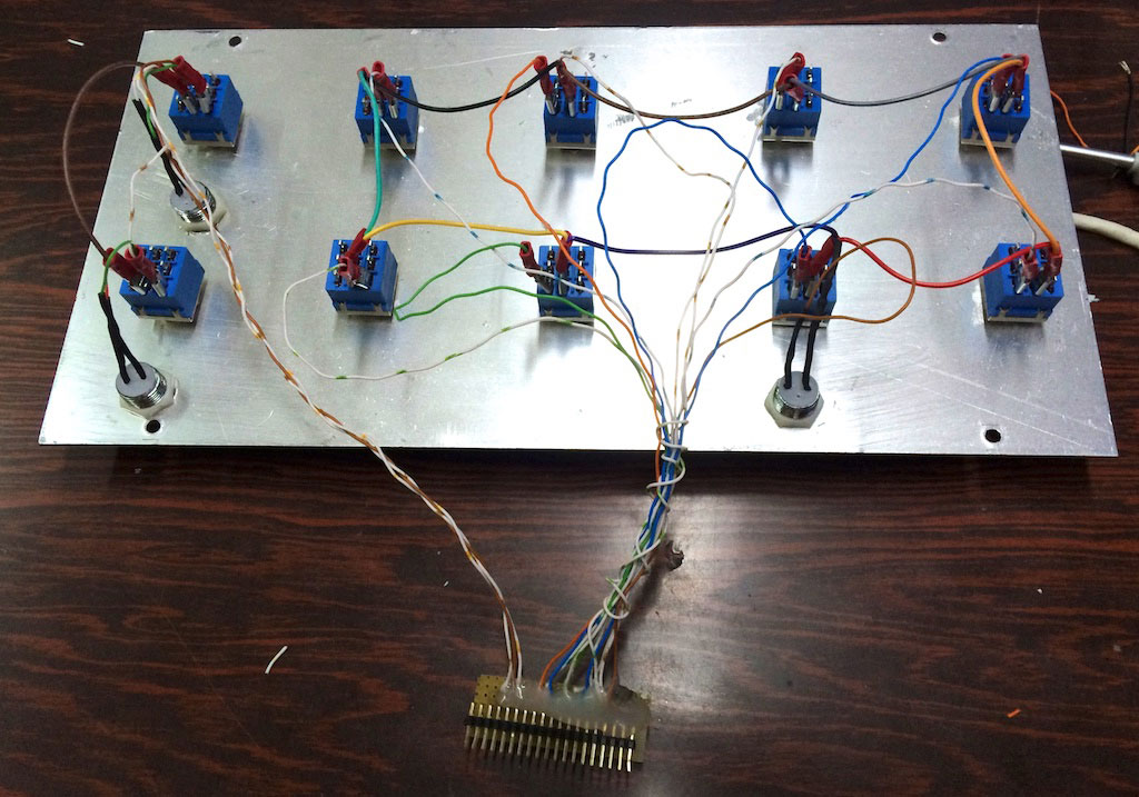
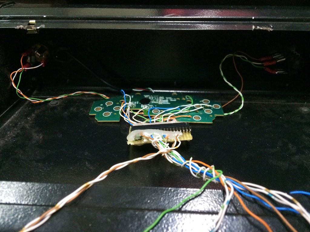
The case is an important factor on the whole construction. It needs to be sturdy and quite large to have all the space available for the switches. The next step is to modify the gamepad board. More advanced gamepads have two boards connected with a ribbon cable. The first board has the microcontroller and the second has all the buttons. So by cutting the removing the second board, all the connections needed are on the ribbon cable. However this is not the case with this cheap one single layer board gamepad. So, after removing the buttons, wires were added for all the connections needed. All the buttons have a pull-up resistor and when they are pressed they are shorted to ground. So the new foot switches which will be added need to have the same characteristics.
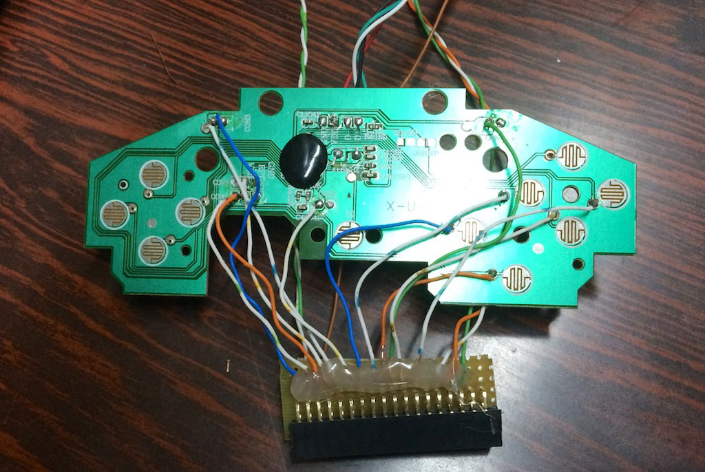
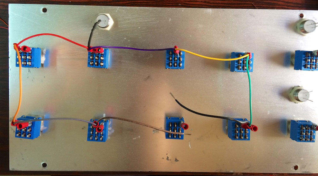
After the case is drilled and all the switches are inserted, the new wiring is done. To simplify repairability and upgradability the connection of the top case switches with the board is done via two custom board connectors. Plastic bezels are inserted to hold the three 10mm LEDs.
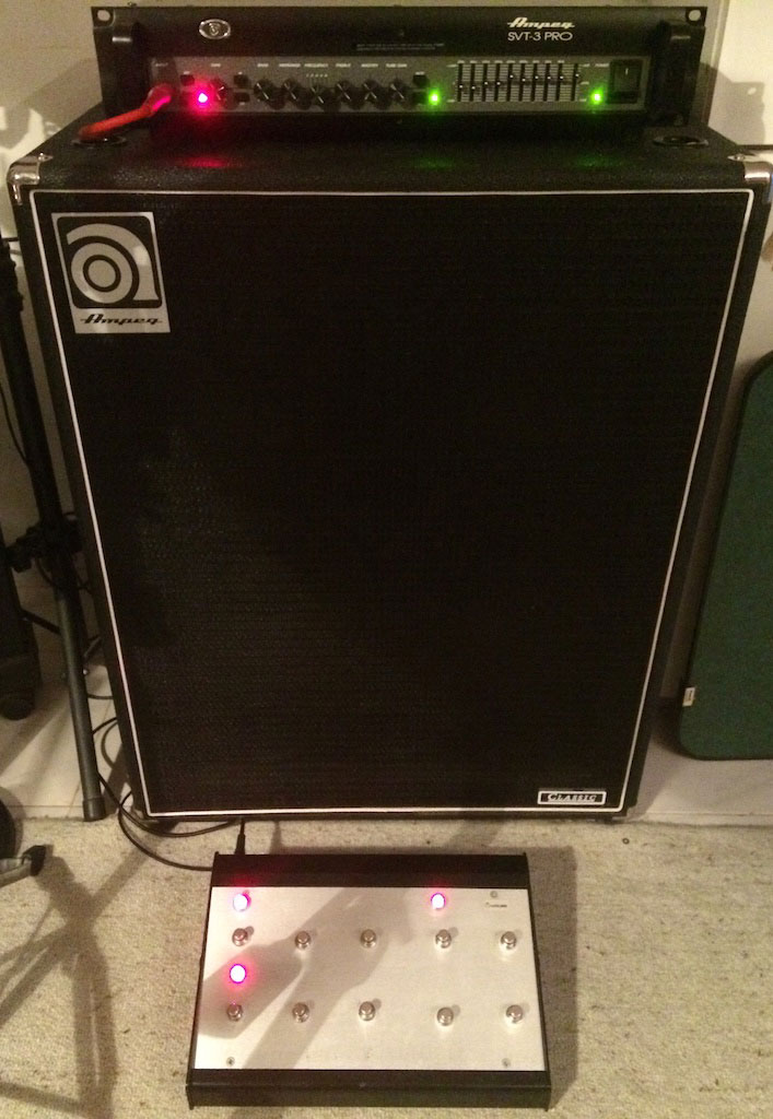
The complete board is inserted with hot glue to hold it on the enclosure. The connector with the amp is inserted on the left and the connector to the volume pedal, is connected on the right. The volume pedal is used as a potentiometer with the analog to digital converter of the gamepad board. The complete pedalboard is shown together with the amp it controls. The two left foot switches control the corresponding buttons on the amp (both activated as shown by the LEDs on the amp and on the board). The LED on the right shows that it is connected to the computer.
The Software
The application used to convert the USB HID events to MIDI messages is MidiHID. The Lua scripting language is used and the application has many configuration examples. Each MIDI message contains a command and two parameters. To use the pedalboard with GuitarRig, each button is activated with the "note-on" command. The note-on is the command number 9, so the script needs to send the following message:
midi.message(9,channel,val)
where the channel is different for each button and val is 0 if off and 127 if on.
For the analog channel the "continuous controller" command (number 11) is used. So the command used is:
midi.message(11,slidermidichan,value)
with the value being between 0 and 127.