Tips for securing a Raspberry Pi visible on the Internet

On a recent project I am involved in, there will be a Raspberry Pi (running Raspberry Pi OS), with a public IP address, accessible on the Internet and always on. This will be the front-end of a power converter, providing communications, diagnostics and control. The system must be low maintenance and operating with up-to-date software versions and must be very well protected. I have grouped the various tips below.

1) OS Settings

  • The OS has a default user called "pi" (with a default password as well). This is well known so a lot of automated attacks try the "pi" username over SSH with various passwords. Disabling and removing this user (by creating first a different administrator account with sudo access) will limit the exposure to this attack.
  • An even better approach is to remove authentication and use a public/private key, instead of a password. The two authentication methods can be active simultaneously, but it's even better if password authentication is fully disabled
  • The Raspberry Pi has by default the SSH service disabled. However, SSH is essential for remote control of the Pi, so it is usually enabled by the user. A change in the default port (to use a port other than 22) will limit the exposure to automated attacks. This can be done via the sshd_config file.
  • Similarly, ports for other services as well (e.g. FTP) can be changed to limit exposure.

2) Firewall

  • The use of a firewall is essential, it acts as a first line of defence and can block multiple attacks. Iptables is the most commonly used firewall in UNIX systems and is very versatile.
  • The default policy for all incoming connections should be "DROP". A "DROP" action rejects the incoming connection with no message back to the sender.
  • With Iptables, a ping response can be blocked. This will reduce the visibility of the machine to the Internet, without someone knowing the address.
  • Another capability that the firewall provides is the ability to limit the visibility of ports based on IP addresses. This can be limited to static IP addresses or group of addresses, for example corresponding to companies or countries
  • Iptables also support to limit the connections to a specific port (with "connlimit"). This can be used to protect the server from DOS attacks

3) Docker

  • Docker containers provide multiple benefits (e.g. flexibility, consistency, fast deployment).
  • Another major benefit, in terms of security, is isolation. A container providing a single service has only its own (limited) filesystem visible
  • The rest of the machine filesystem and services are not visible externally through a given port. A container must be linked to another container in order to provide a connection interface between the two
  • Docker-compose to easily group all of the containers in a stack, to perform actions directly on all the containers.

4) Automatic updates

  • The Raspberry Pi OS uses APT to update the installed packages. The easiest solution for automatic system updates is to create a cron script to do an automatic update and upgrade periodically.
  • An even better approach is to use unattended-upgrades package. This uses a similar approach (periodic check for updates) but is much more customizable.
  • For Docker containers, a similar approach can be done via docker-compose, to pull the up-to-date images and recreate the containers based on the updated images. This can be done again via a Cron script.
  • The Diun container checks for the versions of alll the installed containers. It then notifies the administrator via multiple notification methods, if there is an update on a container.

5) Miscellaneous

  • Another tool to protect against brute-force attacks is fail2ban. The combination of using ports different to the default ones, together with using SSH key authentication instead of password authentication, reduces significantly the exposure to a brute-force attack. The fail2ban tool continuously monitors the server logs and searches for continuous failed attempts. It then blocks the IP address via Iptables.
  • Since the system will not be maintained and checked regularly, an alert system for system operations must be implemented. The easiest way is to use shell scripts that send for example e-mails on major system events (e.g. reboot, login via SSH).
  • The Raspberry Pi includes a Hardware Watchdog. This can be used to reset the system in case of a kernel freeze.

Tracopower THL 15WI Isolated DC/DC converter characterization

For a new power electronics project I am currently working on, the control electronics will be powered by a 12V DC rail, from a grid connected isolated power supply. However, there needs to be a redundancy supply, in case of a grid failure. The Traco Power THL 15-4812WI is suitable for such a task (the power source will be a solar panel). It provides a regulated 12V output, through an isolated 15W DC/DC converter. The datasheet values are quite promising, but there is more data needed not found on the datasheet or on the supplemental documentation, so I got one for testing.

Key values needing to be tested are the efficiency for a wide power and input voltage range, regulation, minimum input operating voltage as well as the protections.

The stated 'typical' efficiency for this model is 89%. As the converter will be operated at a much lower input voltage than the nominal 48V, I measured again the efficiency for different input voltages and input power levels. The results are plotted below. In general, the measurements are in agreement with the datasheet for a load above 40% of the nominal one. An interesting behaviour is shown with the oscillation in the efficiency value. I believe it is because of the variable switching frequency which the converter uses, as a function of input voltage and load. The exact frequency map is not stated in the datasheet.

The next characteristic to check on this dc/dc converter is its regulation for different input voltages as well as loads. It can be seen below that the output voltage changes different as the line input changes for different loads. However, for all the operating points, the  output voltage accuracy is much less than the stated 1%. Moreover, the undervoltage lockout kicks in for any load at 16V, as also stated on the datasheet.

Zooming in on an input voltage close to the minimum required input voltage, it is shown that the converter has a hysteresis for the UVLO protection. The converter starts at an input voltage of 16.7V for any output load. Similarly it turns off just below 16V for any load. An interesting observation is that the output voltage chanes during this input voltage sweep between the ramp-up and the ramp-down. I suspect this is caused due to internal temperature, as it can be seen that the effect is less significant for lower loads and non-existent at zero load.

Concerning overload protection, the datasheet states that the protection kicks in at 1.9A (typical). Indeed, for any input voltage within specification (18V and over) the trip current is very close to this value. For lower input voltages, the trip current values is lower, but this is operation outside of specification anyway.

This converter will be used an isolated step-down converter powering the 12V control electronics from a backup power source, for redundancy. The load will be connected to the converter using a power multiplexer. Therefore, I needed to confirm that the converter to keep its output regulated even if toggling between zero and high load. For this test the load was toggled between 0A and 1A. 


 Zooming in on a step load increase, the voltage undershoot reaches 300mV. There is some limited ringing.

 For the load negative step, the response of the converter is more benign. The overshoot is at 100mV, without any ringing. It is interesting to see that the converter implements pulse skipping to reduce losses. 

Loop compensation in DC/DC converters

The control stability of the feedback loop in DC/DC converters is a quite important subject in power electronics. However, its importance is often lost as the analysis becomes very theoretical, because of all the math that accompanies it. Simulations and experimental tests can always show more pragmatic results about how the theoretical calculations affect the behaviour of the converter during step load changes.

A typical DC/DC converter controller samples the output voltage, compares it with its reference and alters the duty cycle accordingly, to minimize the error between the two values. The components placed on this feedback loop (low power resistors and capacitors), together with the power components characteristics (e.g. LC filter, converter topology) determine the converter stability and response during step changes. The purpose of adding compensation to the error amplifier is to counteract some of the gains and phases contained in the control-to-output transfer function that could jeopardize the stability of the power supply.

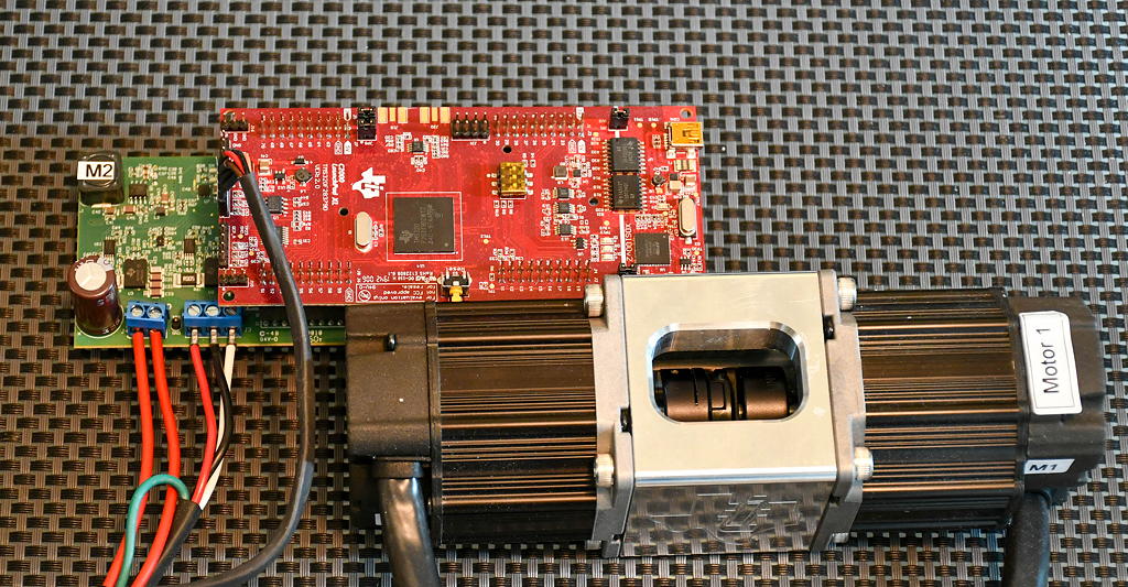
The control theory suggests that for a good loop compensation, the gain margin must be positive, the phase margin between 45 to 60 degrees and the gain curve should have a slope of -20dB/decade at the crossover point. But it's also significant to understand what would the result be if no proper compensation is applied. I have used a full-bridge DC/DC converter, controlled by an ADP1055. The IC samples the output voltage and changes its PWM duty cycle accordingly, based on a Type III network. The filter is digital and can be modified through a GUI, so tests with different loop network settings are almost instant.

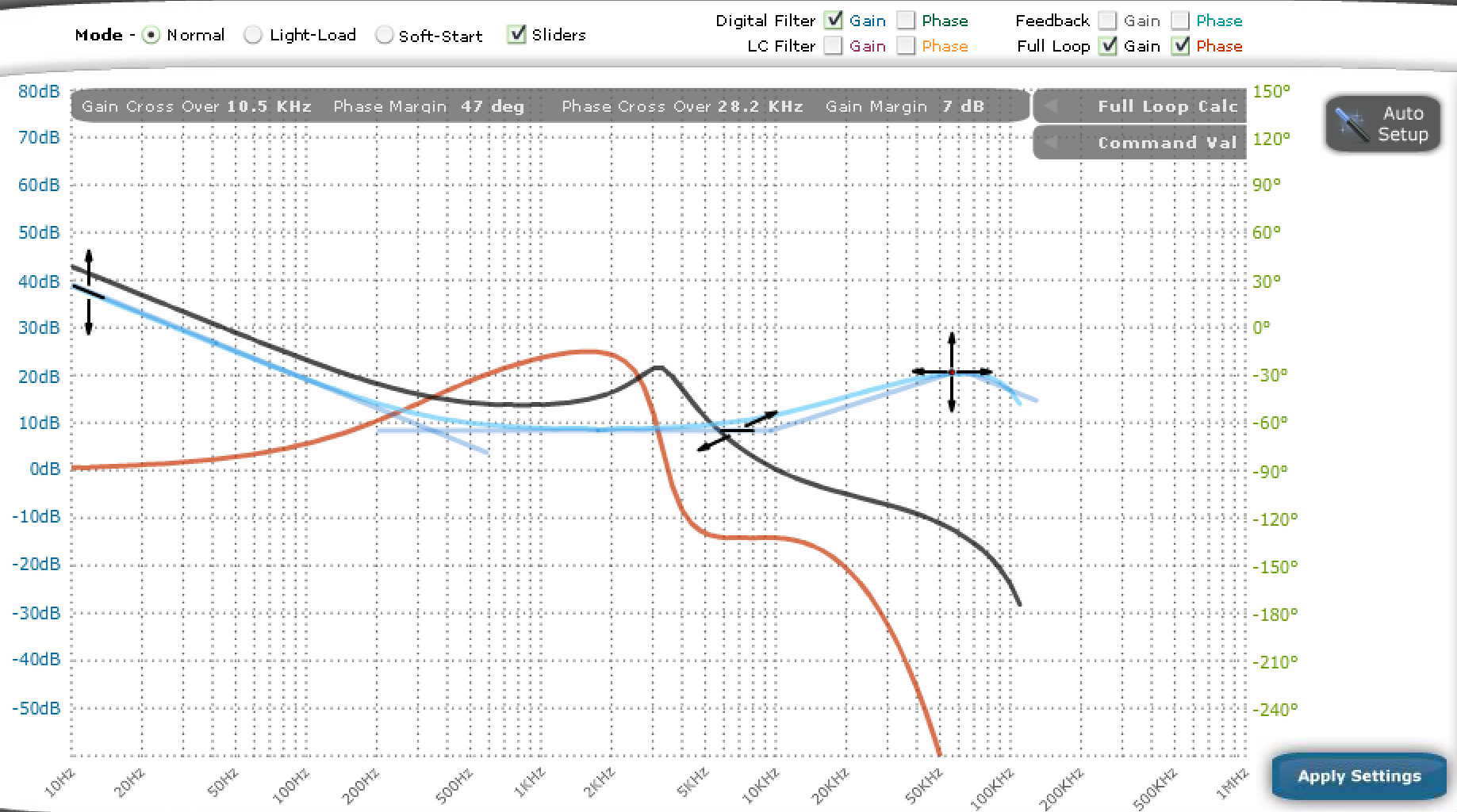
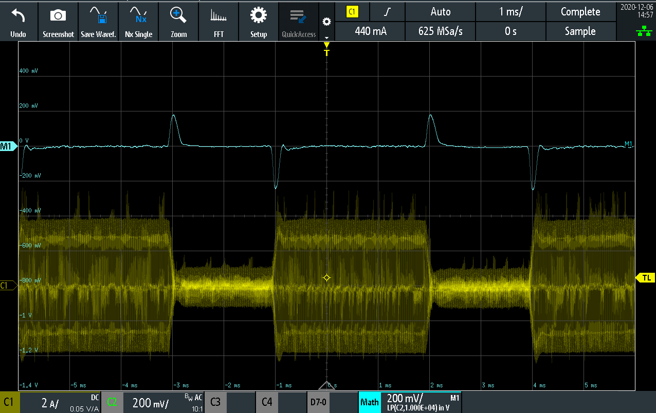
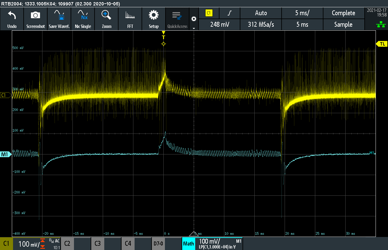
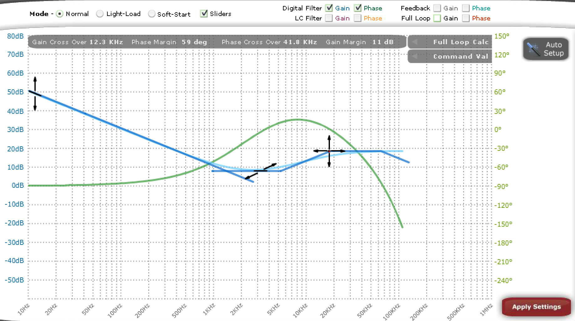
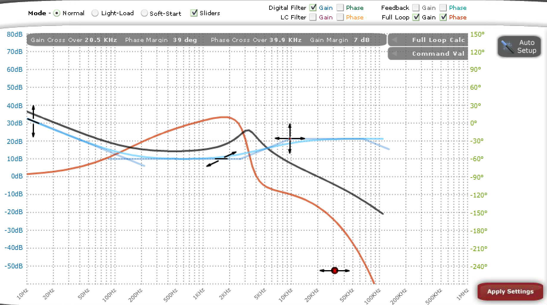
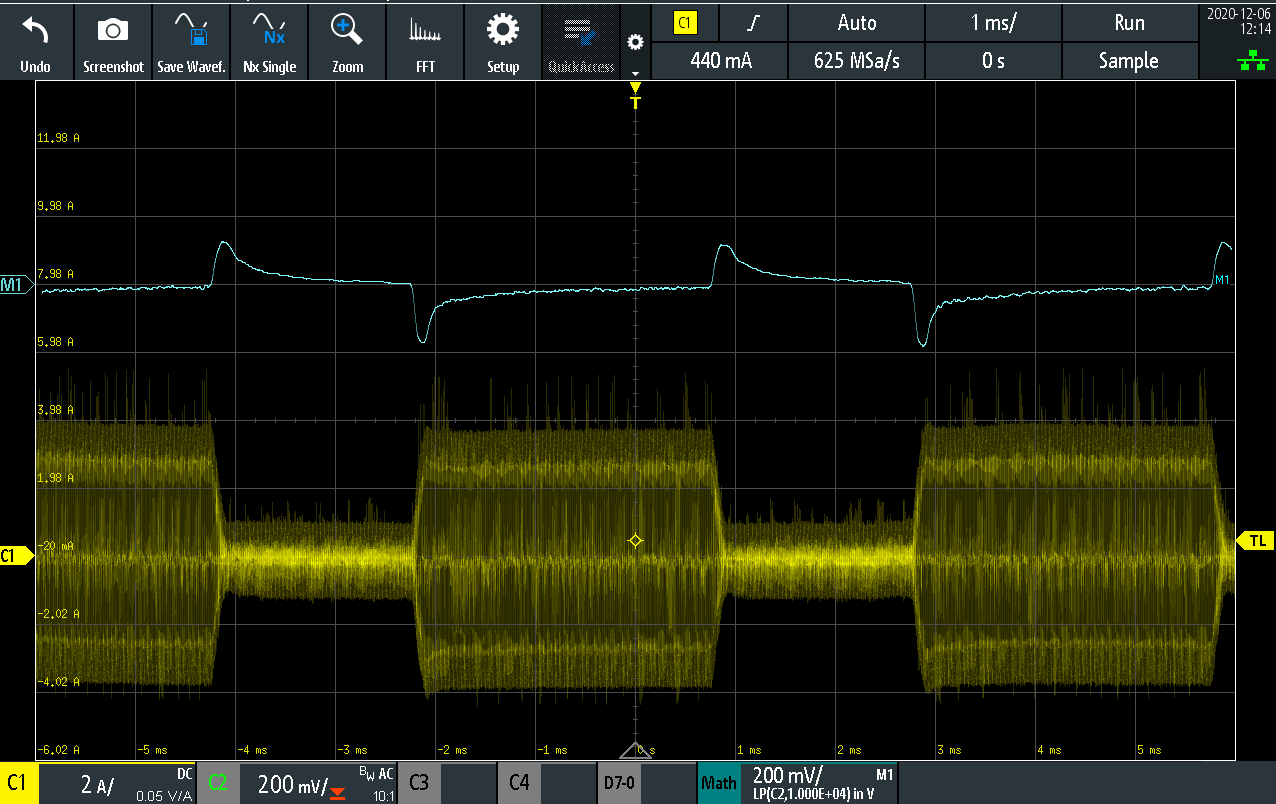
The PWM frequency for all the tests below is 125kHz and the output voltage is sampled once per PWM cycle. A step change of 2A to 15A (10% to 75% of nominal output) and back to 2A is conducted using an electronic DC load. The input side transformer current, as well as the output voltage are measured on the oscilloscope. A 10kHz low-pass filter is applied on the voltage output measurement, for clarity. The GUI settings are shown below. The pole/zero locations of the compensation network can be altered. The GUI automatically calculates the full system frequency response, as well as the gain/phase margins.


Examples of insufficient compensation

Low DC gain

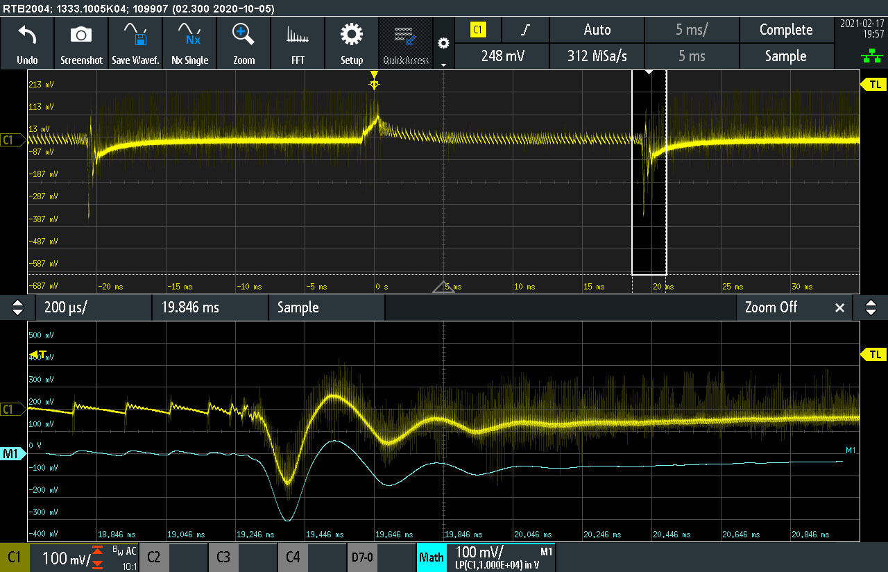
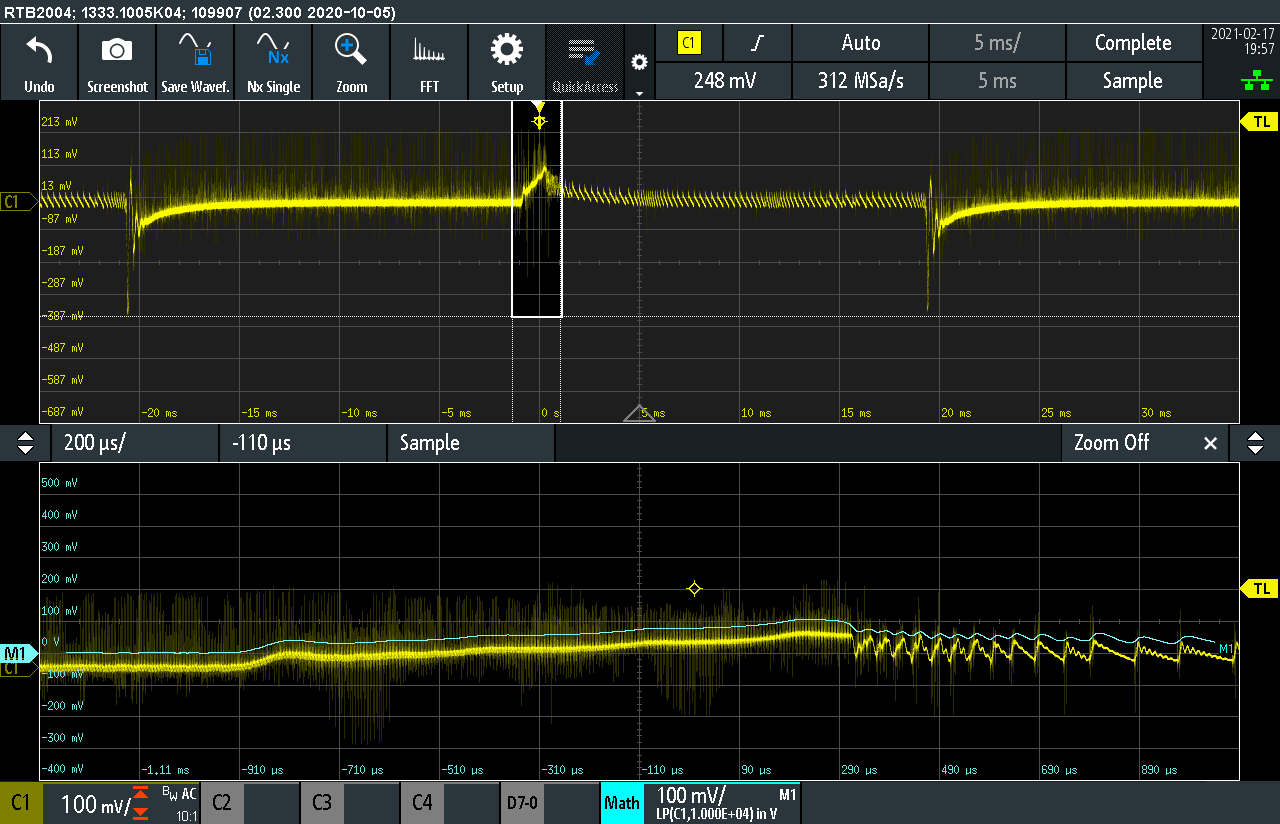
The figures below show the step response of a system which has a low DC (sometimes also called low frequency) gain. Although there is no overshoot on the voltage and the gain/phase margins follow the guidelines, the response is severely overdamped, causing a steady state error which goes to zero after many switching periods.

Underdamped

An opposite response is the one shown below. Notice that both gain and phase margins are negative, something that can cause oscillations to the output voltage and may lead to instability. As can be seen, 5 or more oscillations take place before the voltage reaches steady state.

Oscillation

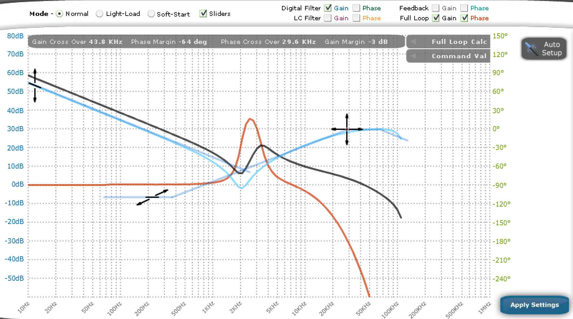
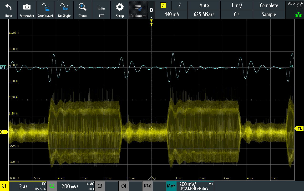
Here is another example of a high loop compensation gain which causes oscillations. Although again, the gain and phase margins do follow the guidelines, the high gain and high crossover frequency cause the system to exhibit a permanent oscillation on the output voltage. This is an unacceptable behaviour on a converter operation. 
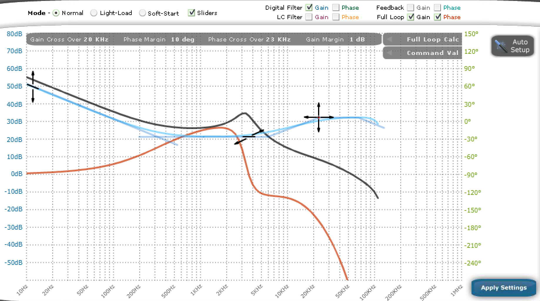
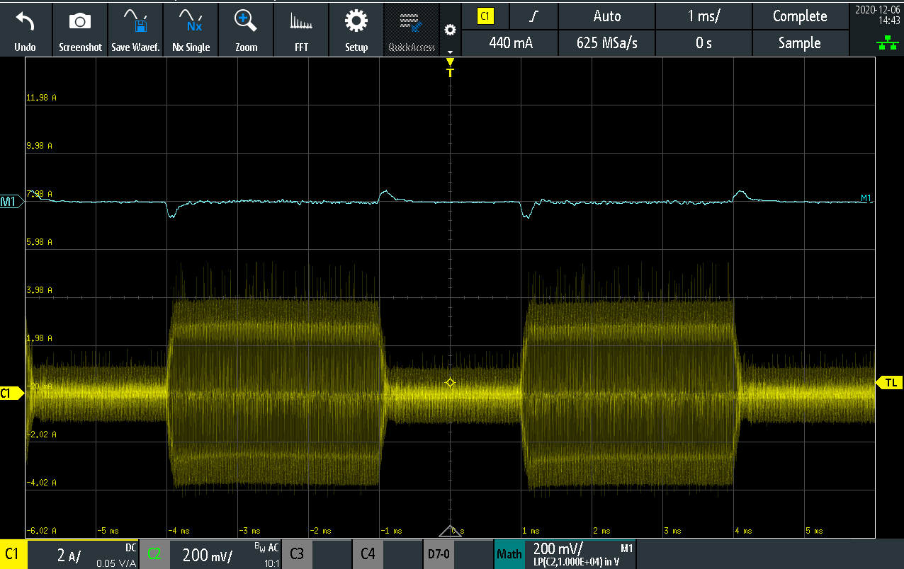
Low margin

The control theory recommends a phase margin above 45 degrees and a gain margin above 3dB. The setup below does not respect any of the two recommendations. However, as can be seen the system exhibits an almost ideal response with a critically damped oscillation, very low overshoot and undershoot, very quick response and no oscillations at steady state. On the other hand, the system is borderline unstable. A small change in the characteristic of any of the components of the system (e.g. due to temperature, change in component values etc.) will make the system oscillate. Operating with such low margins should be avoided.

Examples of good compensation
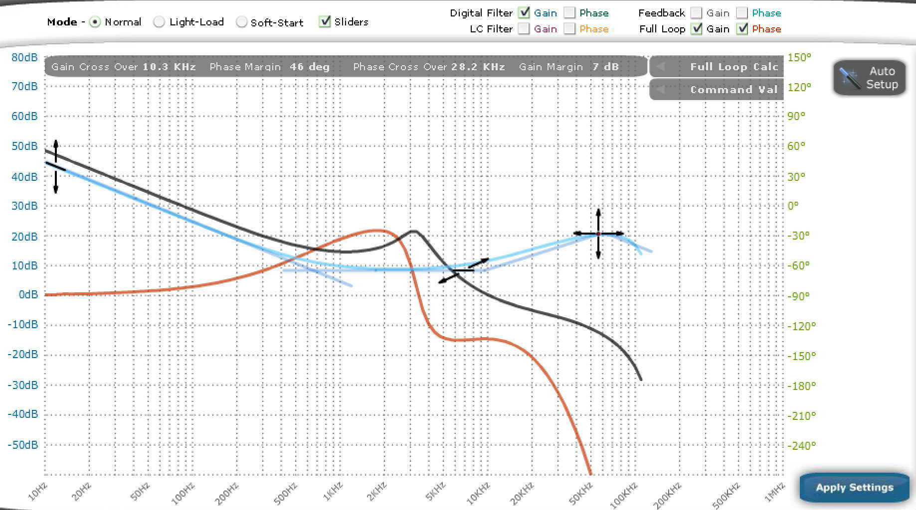
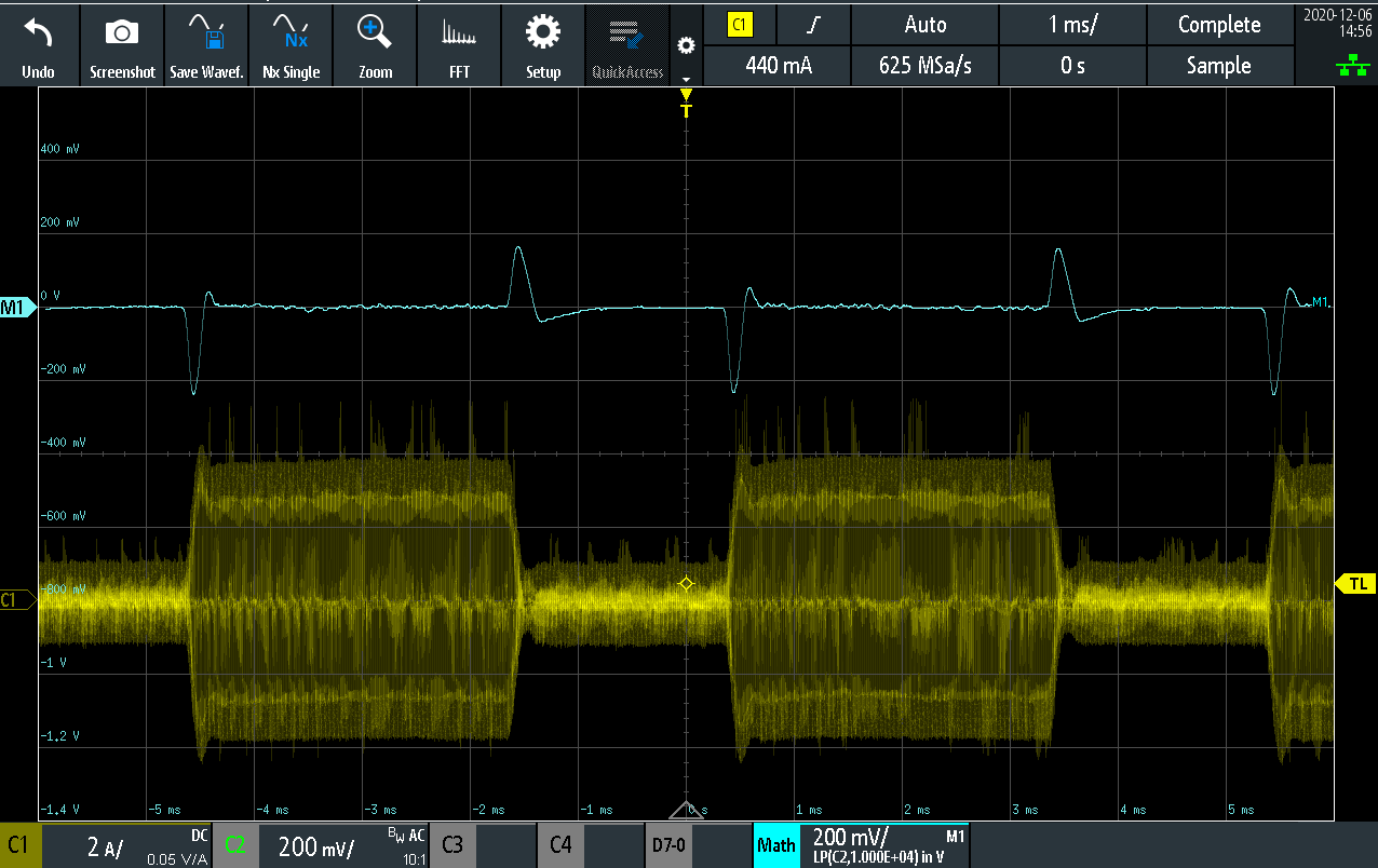
Underdamped

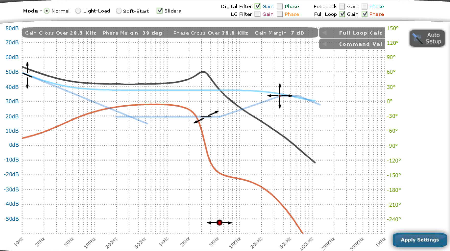
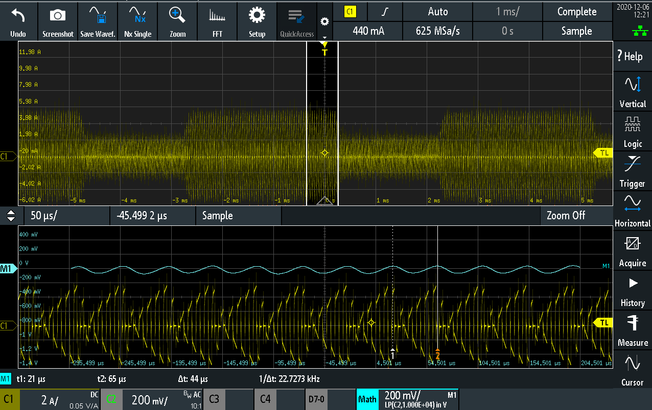
Below examples of proper loop compensation settings are shown. The phase margin is 46degrees and the gain margin 7dB. The response is slightly underdamped, as with a small overshoot and undershoot observed.

Critically damped

As can be seen below, with a small tweak in the compensation values, the response now exhibits critical damping. Observe that the overshoot and undershoot levels are higher compared to when the controller had very small margins. However, these increase margins ensure that the controller will not become unstable, even with small change in the converter component values. 

TI 2MTR-DYNO load motor CCS control

The TI 2MTR-DYNO is a back-to-back permanent magnet synchronous motor system, with the two motors coupled together. The motors are driven by two inverters (Ti offers evaluation boards) and is controlled by a Delfino microcontroller. I have used TI's TMS320F28379D Launchpad to drive one of the two motors, while I was developing the hardware and software for the main motor. The load motor (controlled by the TI software) is in speed control mode, so it keeps a constant speed (positive, negative or zero), which is set by the Code Composer Studio code variables. The TI application note SPRACB8A explains how to get the code, connect the inverter and run the system in various different modes. I will focus in how to setup the system to have a single motor, operating in speed control mode, in order to act as a load during motor control development for the coupled motor.

The characteristics of the 2MTR-DYNO motors are detailed in a previous post. I am using the BOOSTXL-3PhGaNInv module, which consists of a three-phase GaN inverter, together with phase current sensors and a small level of protection circuits. I am have connected the inverter to the lower side BOOSTXL connectors of the Delfino board (J5-J8), as it was easier in terms of assembly. This means that the encoder of the motor, needs to be connected to the QEPB connector (with the triangle on pin1 of the connector). On the BOOSTXL inverter board, the DC supply and the motor phases need to be connected.

On the application code, following the Application Note, I set the 'MOTOR2_DRV' to 'GaN_BP', which is the default and set the 'BUILDLEVEL' to 'FCL_LEVEL5', which is the one for speed control. I have tested all previous build levels beforehand, to ensure the correct operation of the setup and see the voltage/current waveforms of the system and would recommend building on the previous levels as well. However, this post is about using a single motor as a load for the testbech. As soon as I set these parameters in the configuration file (FCL_SFRA_XL_DualServo-Settings.h), I built the project.

I then started the CCS debugger and loaded the key expressions, as shown below. To run the motor as a load for the testbench, the steps are the following:

  1. Hit 'Resume' on the debugger, to start the application code on the processor core
  2. Enable 'Continuous Refresh' on the expressions, to have a live update on the values
  3. Switch on the DC power I usually set it to 30V.  The GaN inverter is compatible with up to 48V
  4. Set 'EnableFlag' to '1'. Monitor the 'IsrTicker' that it's constantly updated
  5. Set 'QepCalFlag' to '1'. Set 'QepCalibSm' to 'Qep2'. This will rotate the motor to find the encoder index
  6. Wait for the encoder index learn. The 'QepCalibSm' will change to 'Done' after that
  7. Set 'Motor2.RunMotor' to 'RUN'. The inverter will start switching
  8. Set 'motor2.pid_spd.param.Umax' to '1.0' and 'motor2.pid_spd.param.Umin' to '-1.0'. This will give maximum capability to the inverter, in order to have the speed follow the reference value, under any torque on the axle.
  9. Set the reference speed by setting the parameter 'motor2.SpeedRef'. The value can be either positive or negative, and it is a ratio of the maximum speed.

TI 2MTR-DYNO motor characteristics

Texas Instruments provides an evaluation kit for Permanent Magnet Motor control. The kit provides two three-phase motors, which are coupled together (motor+load), two inverters and a single microcontroller launchpad, to drive the two inverters. TI also provides software for Field Oriented Control (FOC) with Space Vector Modulation (SVM). Although the TI documentation for the inverter, the microcontroller and the included software. However, there is almost no information about the motors, so I had to search the internet, to see pictures on how to connect the motors to the boards for example, or read the TI code for the ratings of the motor.

The motor is the M-2310P-LN-04K Brushless Three-Phase permanent magnet motor. The datasheet of this motor can be found on the Teknic website. The motor has an internal encoder of 4000counts per revolution. It also has a 120degree commutator, which is less preferable for Field Oriented Sensored Control.

The motor comes with the Molex Mini-Fit connector. It is then output to two low-power connectors (encoder and commutator) and has the high power cables available as well.

Encoder connector (J6)

The encoder connector is a standard 5-way single row 2.54 spacing connector. The pinout is shown below:

1 - Blue: Encoder A pulse

2 - Orange: Encoder B pulse

3 - Brown: Encoder I pulse

4 - Red: 5V power supply (125mA at idle)

5 - Black: Ground

Pin 1 is considered as the the pin with the ^ symbol. The encoder count is 4000 per mechanical revolution.

Power connections

All the wires are AWG16.

Black: Phase A

Red: Phase B

White: Phase C

Motor Characteristics

The motor has a sinusoidal Back-EMF. The back-EMF factor is 4.64Vp/krpm (line to line) [based on the datasheet]

The motor has 4 pole-pairs [based on the datasheet]. The resolver offset needs to be learned by applying fixed vectors to the windings.

The Maximum Continuous torque is 0.2754Nm [based on the datasheet, converting from oz-in]

Based on the above, the torque constant 0383725Nm/Ap, whereas the maximum Iq current is 7A.

On the motor label, the rated speed is mentioned, which is 6000rpm (mechanical). The label also states that the rated continuous current is 7.1A.

Concerning electrical characteristics, I have done the following measurements to determine the inductance and resistance:

Phase resistance: Measured with a DMM (4-wire measurement) the phase to phase resistance, when the TI kit molex connector was connected. The average phase to phase resistance was 777mΩ (at 20degC), leading to an average phase to neutral resistance of 389mΩ. The value mentioned on the datasheet is 720mΩ (phase to phase), which perhaps doesn't considers the extra harness.

Concerning inductance, the datasheet states 400uH (phase too phase), which doesn't say much about the motor characteristics. NXP has a good application note, which explains how to align the rotor, to measure the Ld and Lq value, applying step voltage changes on the windings. I did follow the application note to align the rotors (applying fixed vectors), but then used a network analyzer to determine the inductance for different frequencies. The results of these measurements are shown in the figure below.