For a new power electronics project I am currently working on, the control electronics will be powered by a 12V DC rail, from a grid connected isolated power supply. However, there needs to be a redundancy supply, in case of a grid failure. The Traco Power THL 15-4812WI is suitable for such a task (the power source will be a solar panel). It provides a regulated 12V output, through an isolated 15W DC/DC converter. The datasheet values are quite promising, but there is more data needed not found on the datasheet or on the supplemental documentation, so I got one for testing.
Key values needing to be tested are the efficiency for a wide power and input voltage range, regulation, minimum input operating voltage as well as the protections.
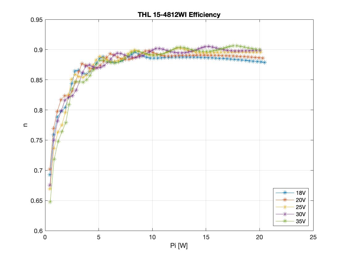
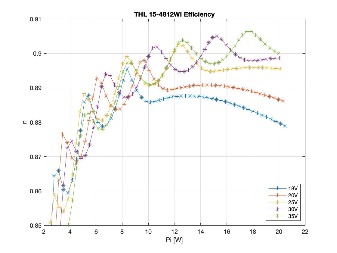
The stated 'typical' efficiency for this model is 89%. As the converter will be operated at a much lower input voltage than the nominal 48V, I measured again the efficiency for different input voltages and input power levels. The results are plotted below. In general, the measurements are in agreement with the datasheet for a load above 40% of the nominal one. An interesting behaviour is shown with the oscillation in the efficiency value. I believe it is because of the variable switching frequency which the converter uses, as a function of input voltage and load. The exact frequency map is not stated in the datasheet.
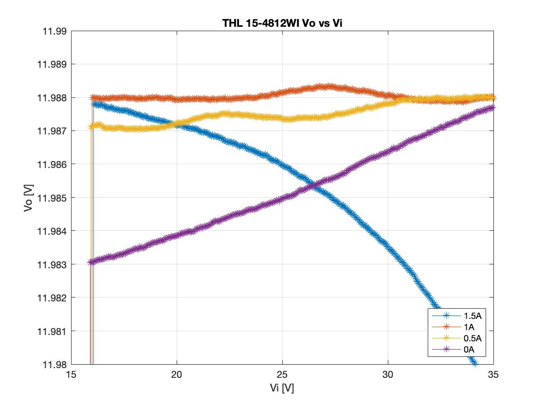
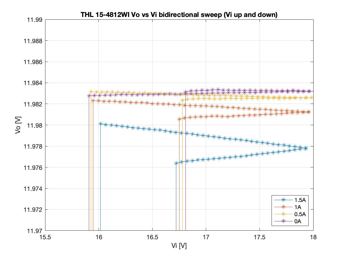
The next characteristic to check on this dc/dc converter is its regulation for different input voltages as well as loads. It can be seen below that the output voltage changes different as the line input changes for different loads. However, for all the operating points, the output voltage accuracy is much less than the stated 1%. Moreover, the undervoltage lockout kicks in for any load at 16V, as also stated on the datasheet.
Zooming in on an input voltage close to the minimum required input voltage, it is shown that the converter has a hysteresis for the UVLO protection. The converter starts at an input voltage of 16.7V for any output load. Similarly it turns off just below 16V for any load. An interesting observation is that the output voltage chanes during this input voltage sweep between the ramp-up and the ramp-down. I suspect this is caused due to internal temperature, as it can be seen that the effect is less significant for lower loads and non-existent at zero load.
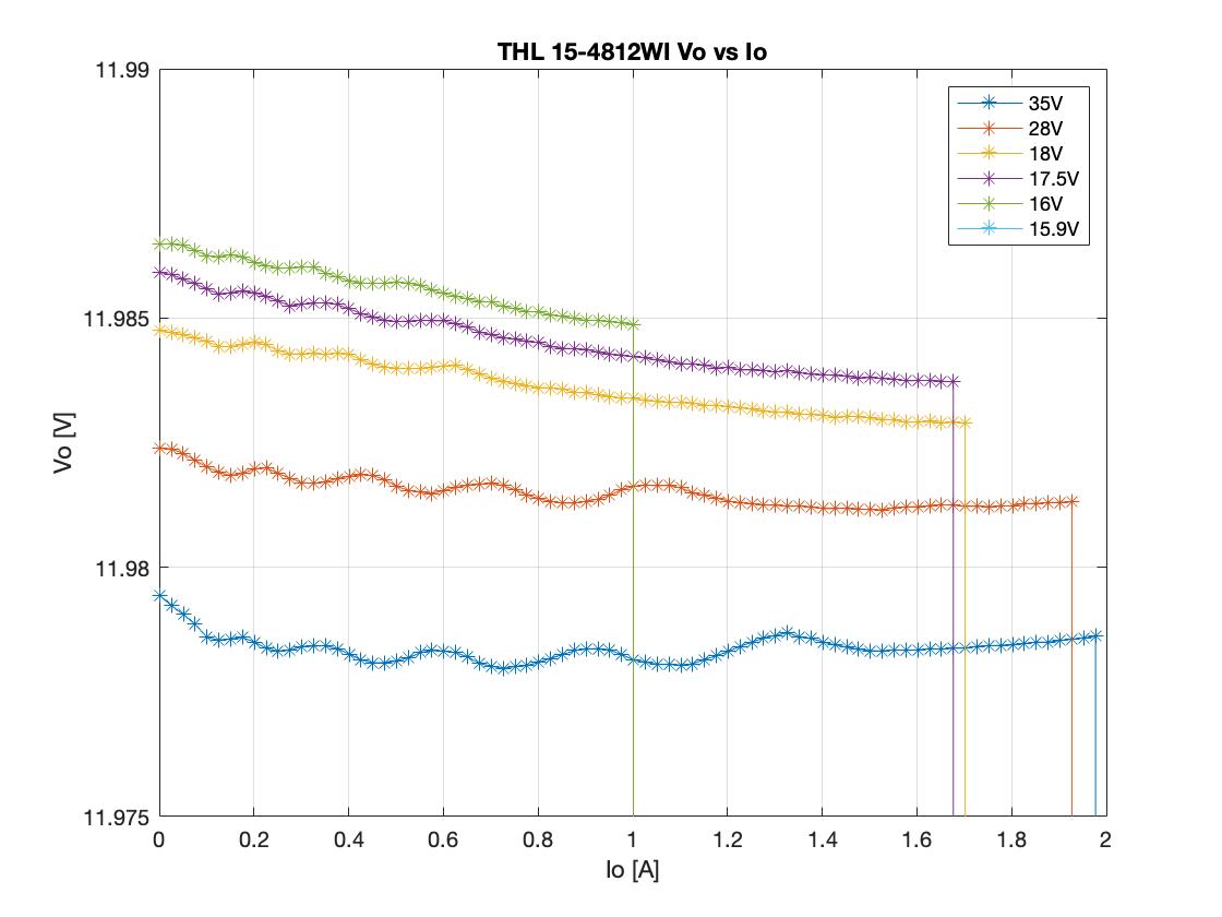
Concerning overload protection, the datasheet states that the protection kicks in at 1.9A (typical). Indeed, for any input voltage within specification (18V and over) the trip current is very close to this value. For lower input voltages, the trip current values is lower, but this is operation outside of specification anyway.
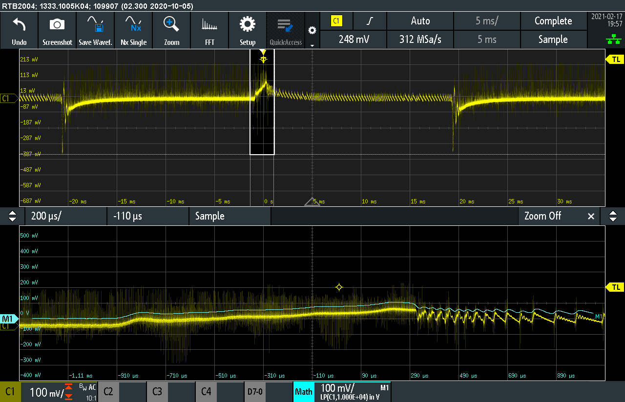
This converter will be used an isolated step-down converter powering the 12V control electronics from a backup power source, for redundancy. The load will be connected to the converter using a power multiplexer. Therefore, I needed to confirm that the converter to keep its output regulated even if toggling between zero and high load. For this test the load was toggled between 0A and 1A.
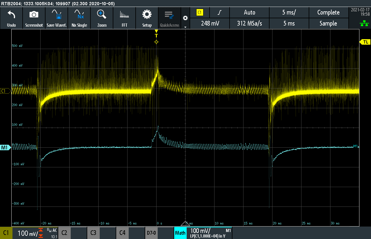
Zooming in on a step load increase, the voltage undershoot reaches 300mV. There is some limited ringing.
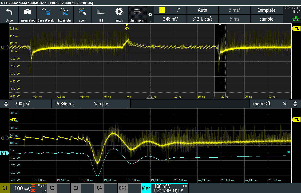
For the load negative step, the response of the converter is more benign. The overshoot is at 100mV, without any ringing. It is interesting to see that the converter implements pulse skipping to reduce losses.