The Keithley DMM6500 digital multimeter supports the use of scanner cards. Scanner cards are multiplexers which extend the number of channels that can be connected in a multimeter and can be sampled (almost) simultaneously. Officially, the DMM6500 supports the 2000-SCAN 10-channel card as well as the 2001-TCSCAN 9-channel with cold junction compensation (used for thermocouple measurements).
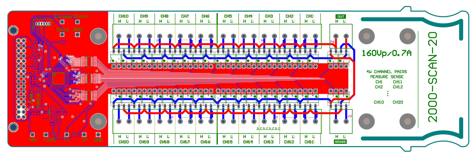
I have been using my DMM6500 for performing automated measurements and a scanner card would also help with that. However, all those scanner cards use mechanical relays, which means a finite contact life as well as noise during operation. Cozdas has created a solid state relay scanner card, using an Arduino microcontroller. I liked the idea of having electronic switches, so I decided to design a similar one. Moreover, the card is designed to replicate the 2000-SCAN-20 card, which is a 20-channel card. The DMM6500 does not officially support this card, however tests show that it works fine.
The Interface
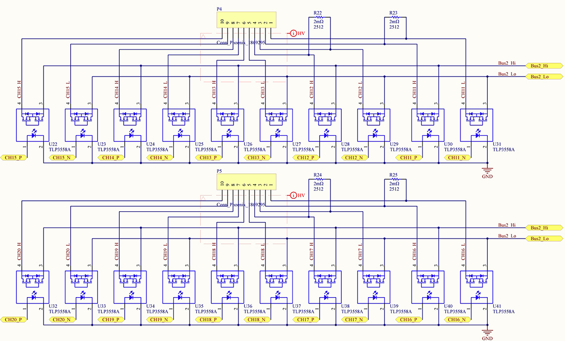
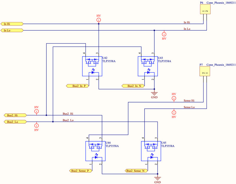
Each scanner card (either 10-channel or 20-channel one) is mounted inside the multimeter and is controlled through a DIN connector. The multimeter commands the closure of each relay per the user settings and timings. The scanner card outputs the signal to banana plugs which are connected to the multimeter terminals (usually in the back as it is closer to the card). Each card has two buses (each bus contains half of the channels). All the channels can connect to the primary bus, which connect to the multimeter input terminals. However, half of the channels can be connected to the second output, which goes to the multimeter sense terminals. These channels can be used in 4-wire mode, to measure resistances with Kelvin connections.
The card is detected by the DMM through two ID pins. Depending on where those two pins are connected, the card can be recognized as a 2000-SCAN/2001-TCSCAN card or as 2000-SCAN-20 card. The connector also supplies 5V to power the card components.
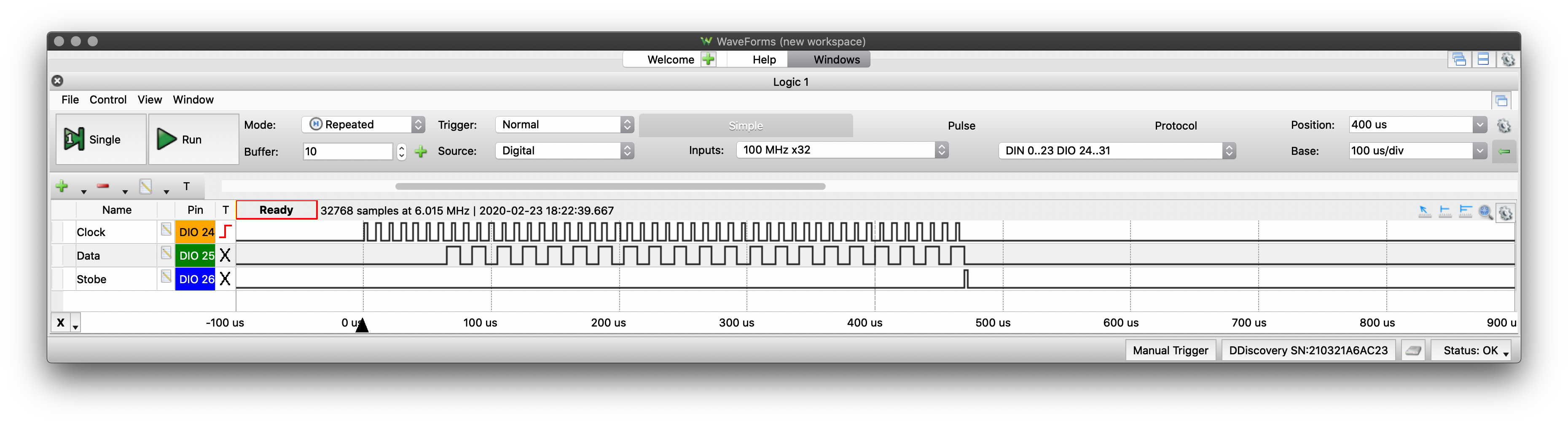
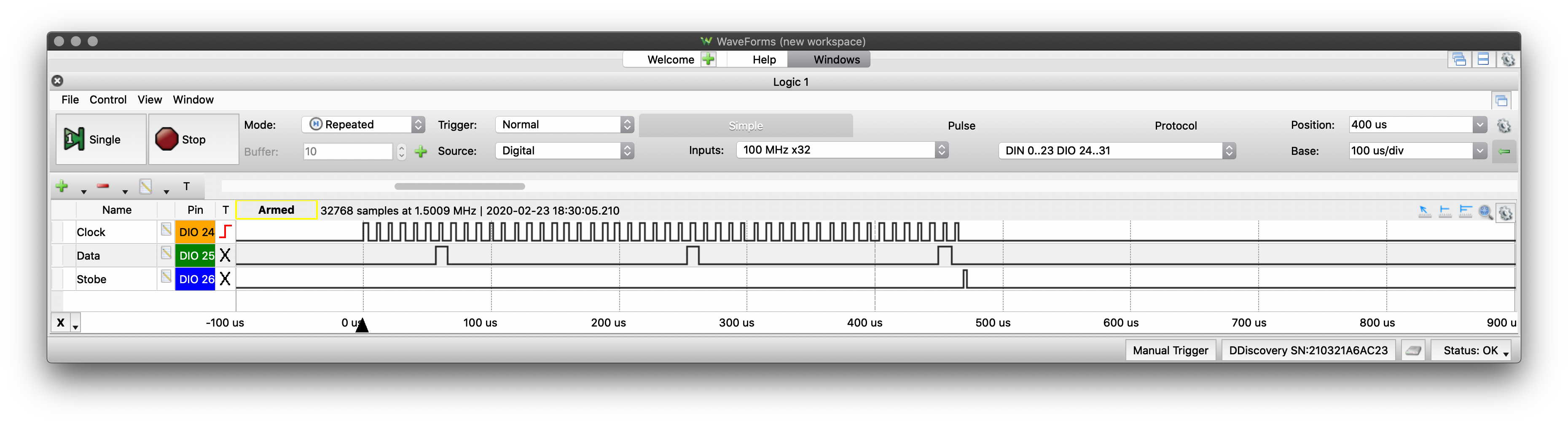
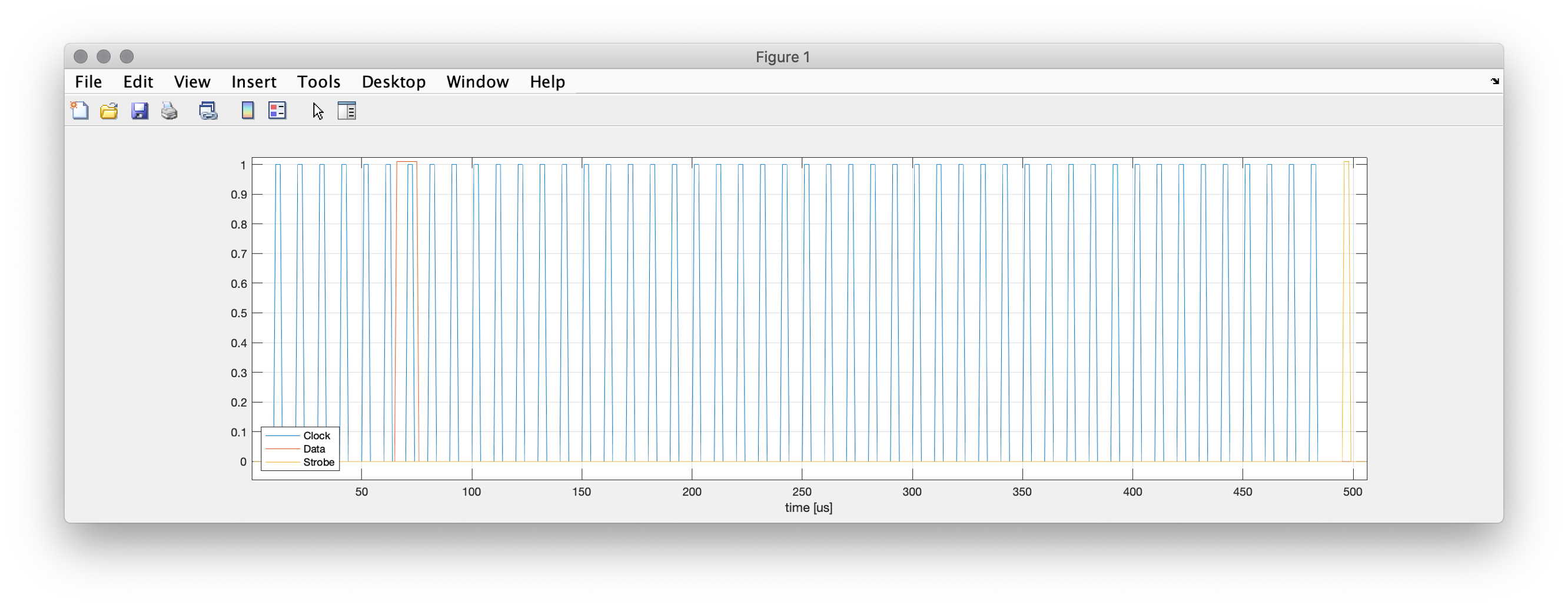
The original scanner cards have the relays controlled by shift registers. A clock (100kHz, 33% duty cycle), data (10us, registers at positive edge) and strobe (3.3us) signal combination is used to control the relays. For the 2000-SCAN-20 card, the DMM sends 64 pulses. The even pulses are used to turn off the relay and the odd pulses are used to turn them on. There is also a reset signal, used to keep the card in reset during connection.
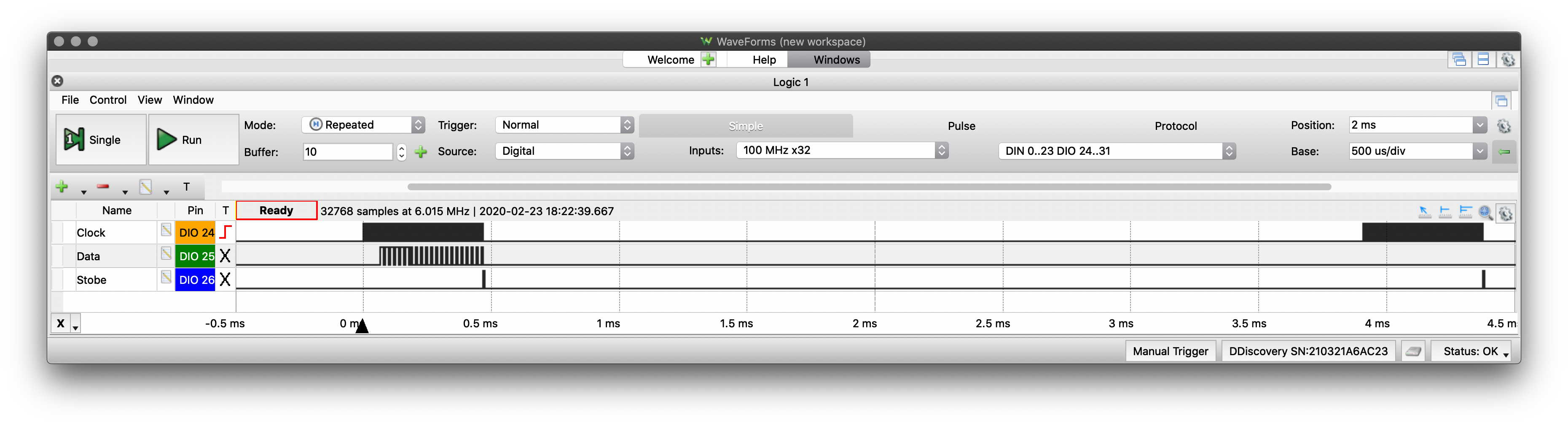
In the images below, CH1 is commanded to turn on. As can be seen, two pulse sequences ares sent. The first one turns on the imaginary mechanical relay. The second one, 3.75ms afterwards, stops energising the relay.
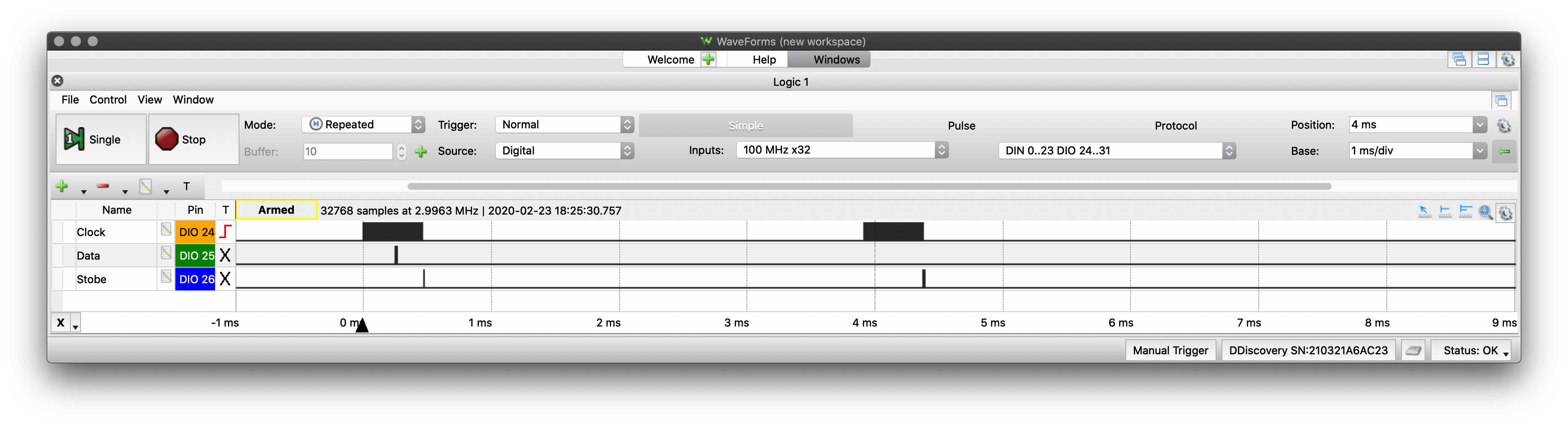
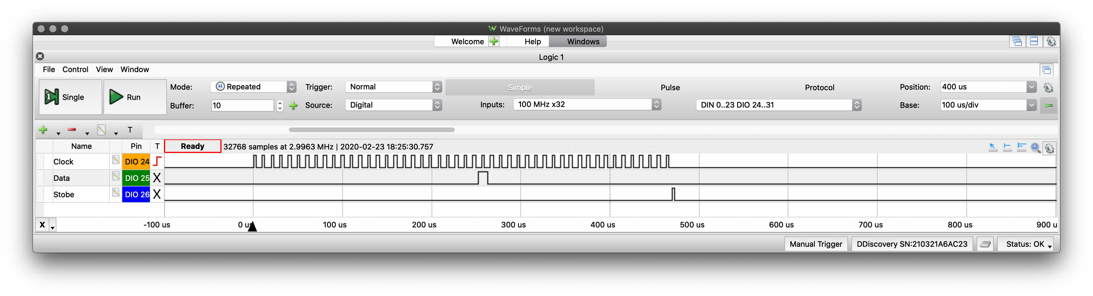
The same sequence happens for turning off a relay, with two pulse sequences, 3.75ms apart, as shown on the images below, for CH1 again.
The difference between the two pulses is the clock rising edge where the data line goes high. On the odd clock rising edges, a data high is used to turn on a channel. On the even clock rising edges, a data high is used to turn off the channel. The sequence of channels is 11->12->13->14->15->16->17->18->19->20->1->2->3->4->5->6->7->8->9->10->main (bus1) relay->4w measurement (bus2) relay.
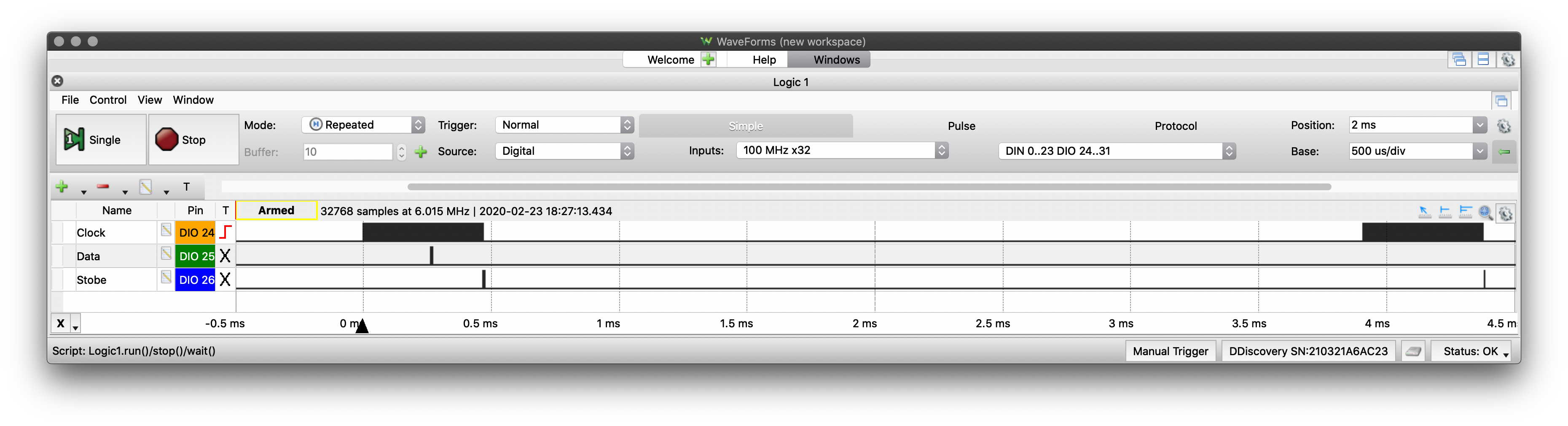
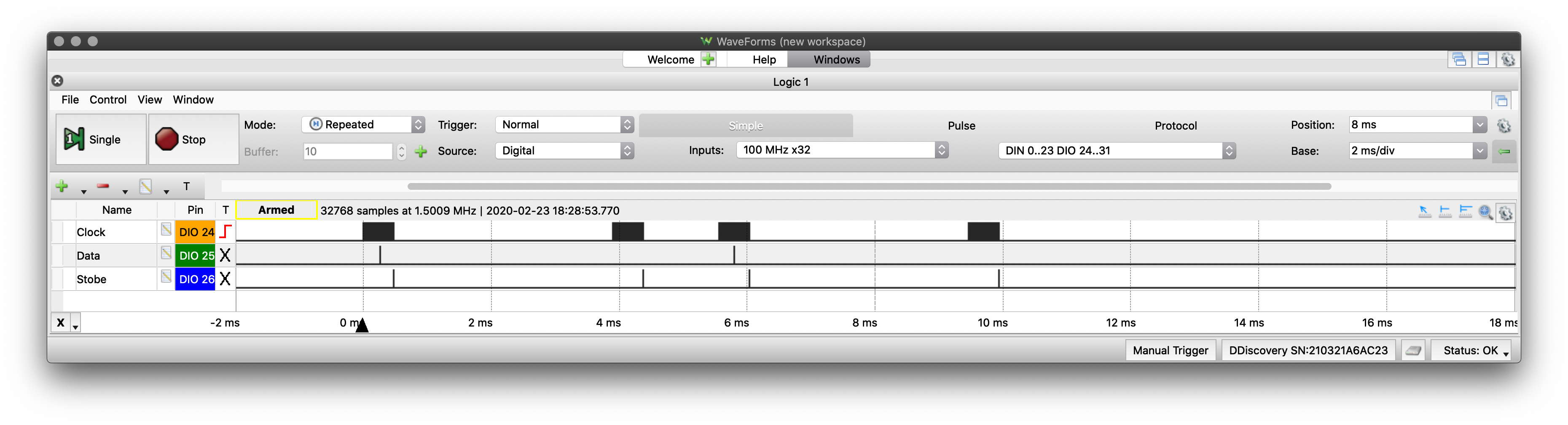
During power-up, all the relays are commanded to turn-off. This is achieved by sending pulses on all the even clock rising edges, as shown below.
For consecutive measurements, the DMM6500 first turns off one channel and then immediately turns on the second one, as shown below.
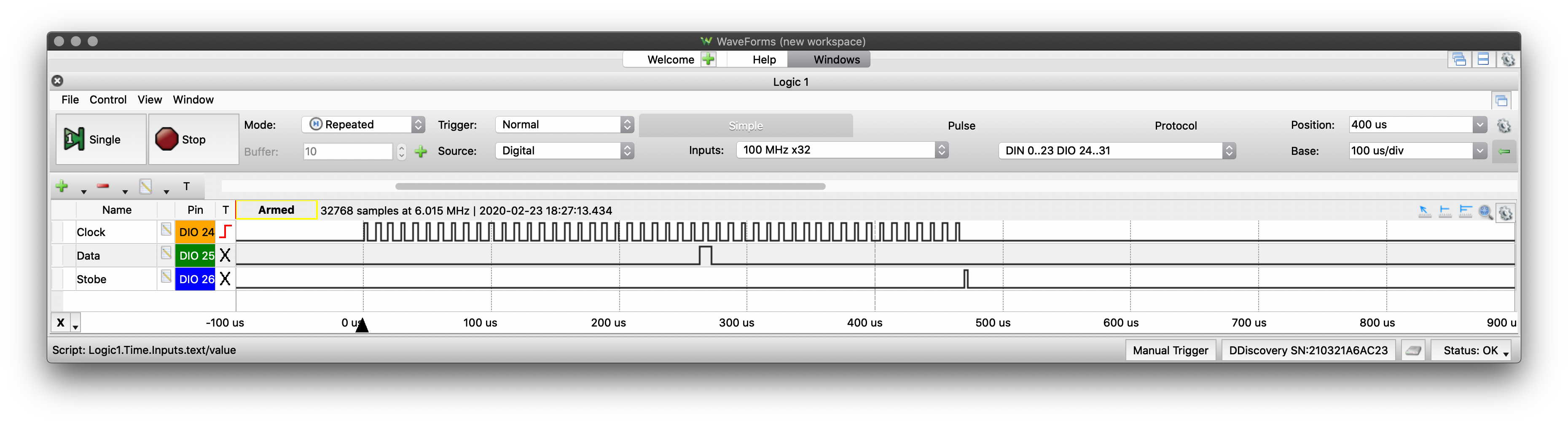
Finally, for 4-wire measurements, the DMM will activate two relays at the same clocking sequence (the channel relay as well as the bus2 relay), as shown below, for CH1 (paired with CH11).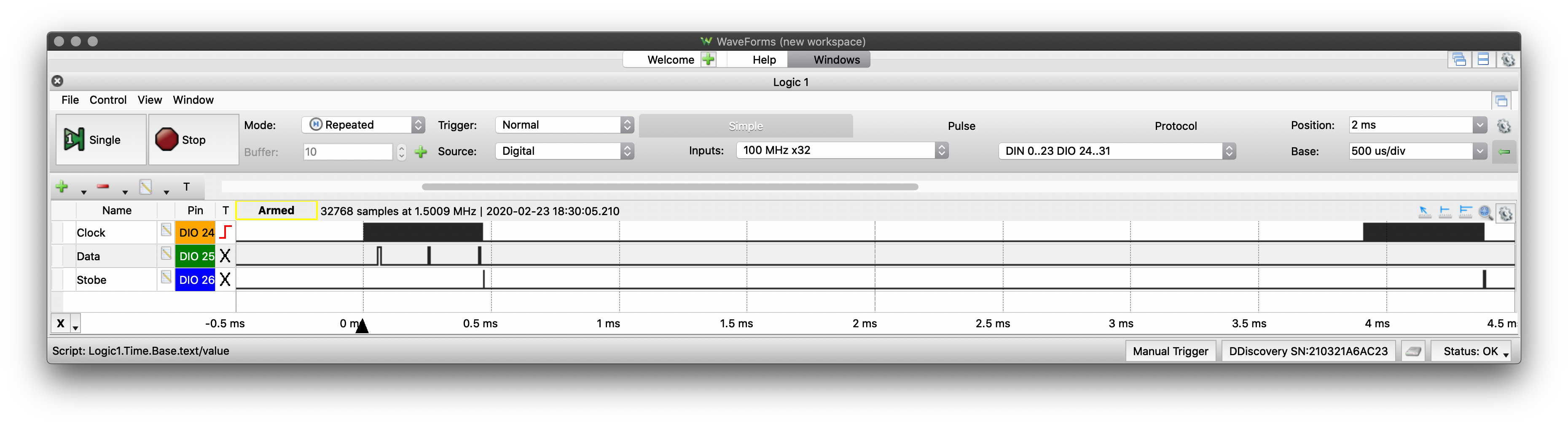
The Hardware
Components
The most important component for the scanner card is the relay. Mechanical relays provide good channel isolation (GΩ of isolation resistance), very small contact resistance (<1Ω), high voltage capability and high current capability as well. The switching times however are small, their lifetime is limited and they make a lot of noise. Solid state relays are silent and with increased lifetime. However, all of their electrical characteristics are significantly worse than the mechanical relays. This doesn't mean that they are unfit for purpose, though the capability of the scanner card will be limited. After a search of what was available, I used the Toshiba TLP3558A photorelays, the same components which were used on the CozScan2020 scanner card. The relays offer the best compromise in voltage withstand (maximum recommended 160V), contact resistance (2Ω maximum, 0.9Ω typical), off leakage (1uA maximum, 40nA typical) and current handling capability (0.7A). On resistance is important as it is connected in series to the internal 10ΜΩ multimeter resistance, affecting the accuracy of the measurement. However, it is also important as the multimeter needs to have a maximum of 5Ω resistance between the sense terminals and the input terminals. The original 2000-SCAN-20 card has a 60V/0.5A specification with mechanical relays, so it is still an upgrade.
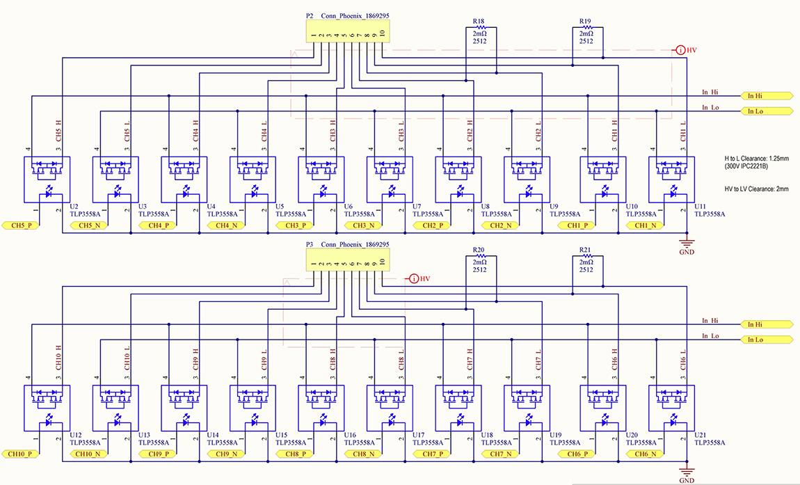
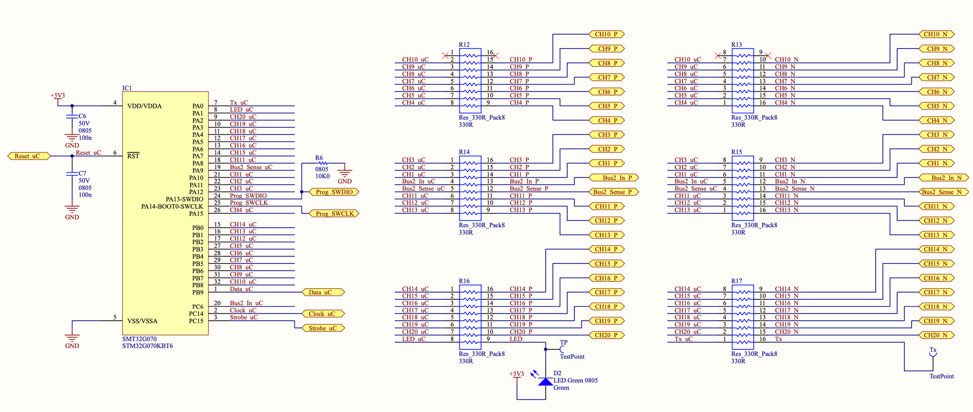
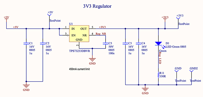
In terms of the relay control, I selected to use the STM32G0 microcontroller. It comes in a LQFP-32 package and can control all of the SSRs without any port extender. It needs 3.3V to operate, therefore a linear regulator was used as well. Finally, Phoenix terminals with 5.08mm pitch were used to ease the connection of the wires to the different channels of the scanner card. As I am using individual resistors to drive the positive and the negative LED of each channel, I used some 16-pin resistor networks to ease assembly. For the 2 free ports that were remaining on the package of the microcontroller, I use one as a UART Tx for diagnostics during development and the second one for a diagnostic LED.
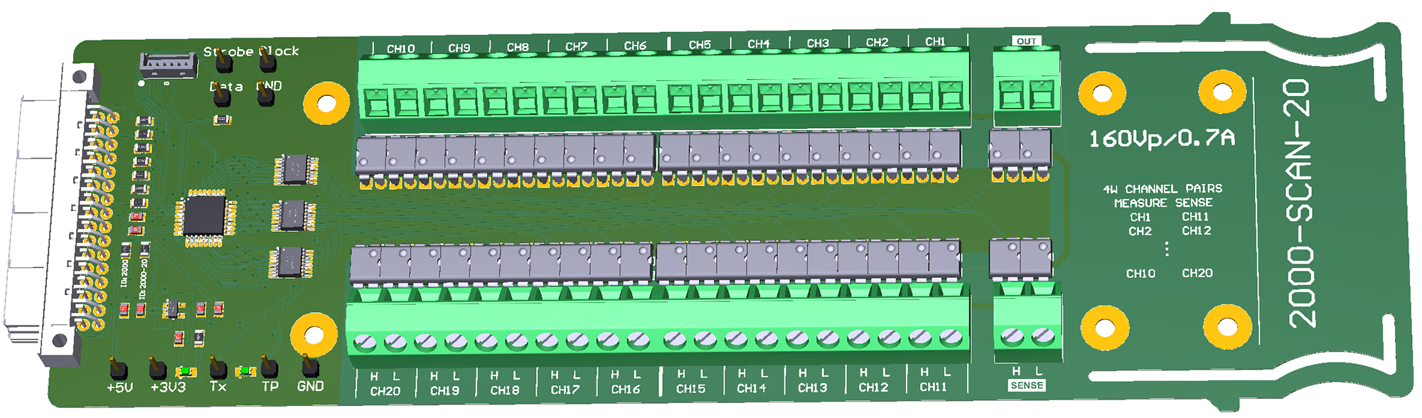
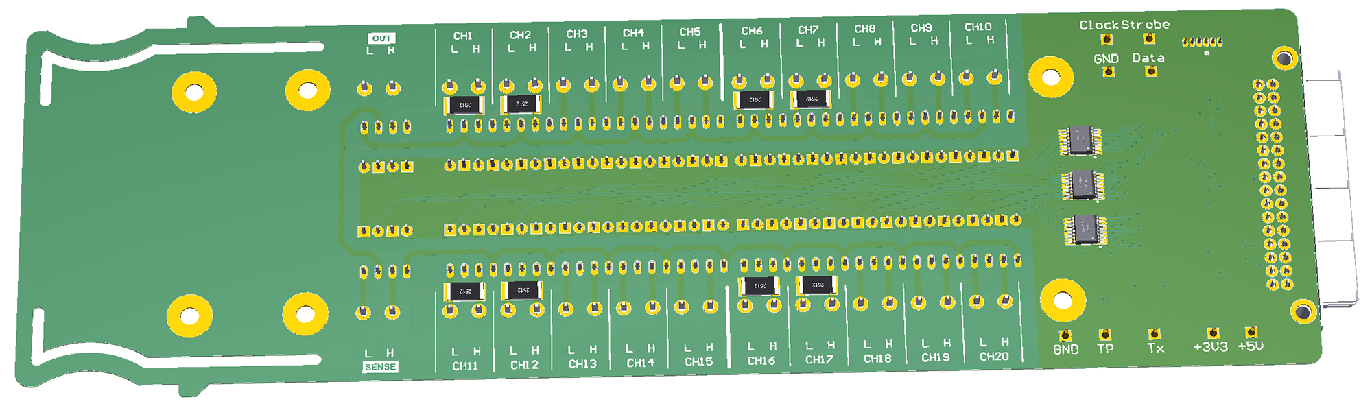
PCB
The PCB width must be 67mm in width, in order to fit in the cartridge area of the multimeter. It must also be at least 203mm in length, to be accessible from the back of the multimeter. I used voltsandjolts' PCB outline, as shown in the EEVblog forum. It has nice cutouts to form a handle in order to put the card in an out. I prefered to place the output connectors near the edge of the card, as they will always be used. I've also put a total of 8x 2512 resistor footprints, in case I want to convert some of the channels to current measurement ones using shunt resistors.
The relays are rated for 160V (recommended), 200V absolute maximum. Although this scanner card will not be used for any grid connected measurements, I still used a clearance of 1.25mm between the terminals (which corresponds to 300V isolation) and 2mm between the control signals and the channels.
The Software
Replicating the DMM control signals
During the development of the STM32 firmware, I needed to have the DMM control signals available to verify the scan card operation outside of the multimeter. Digilent's Analog Discovery (or Digital Discovery), can record signals from the logic analyzer and replicate them.
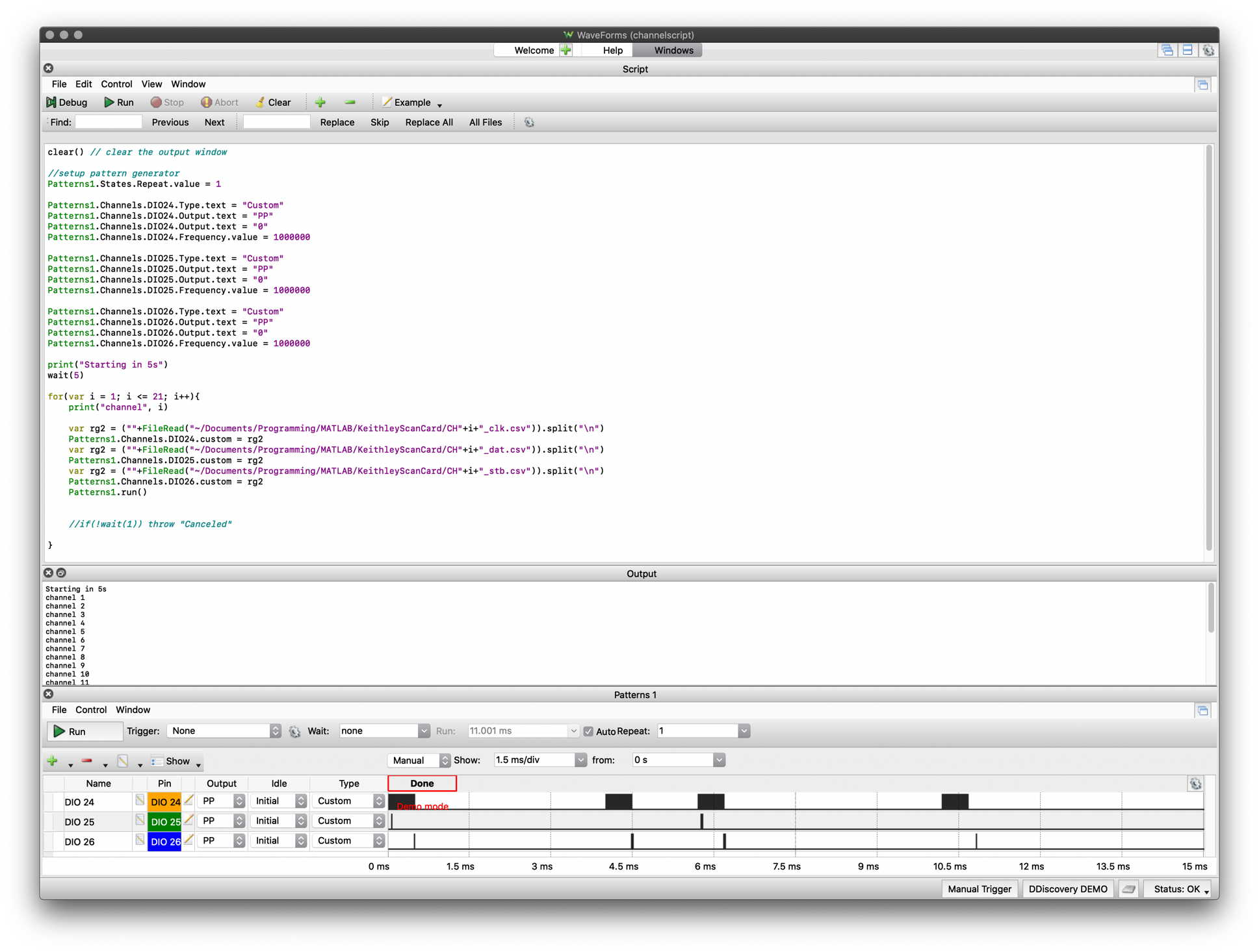
However, since I would want to test different scenarios to ensure that the code works for each potential command, I opted to generate the signals myself. The Analog Discovery can generate patterns from CSV files. I used MATLAB to create those CSV files, an example of a pattern to turn on CH1 is shown below.
Waveforms, the application which controls the Analog Discovery can be controlled through scripts. I wrote a script to load the CSV patterns generated from MATLAB and turn on/off a channel each second or perform any other channel combinations.
Microcontroller software
The STM32 code is fairly straightforward. First, all of the GPIOs are initialized, together with the clock PLL and the UART. The microcontroller operates using interrupts. As soon as a positive clock edge arrives, the microcontroller saves the data value in a shift register. As soon as a strobe pulse arrives (again, detected using an interrupt), the data is decoded and the action is performed. For the 2-pole relays (all of the channels), the action is simple. In case a command for the bus2 multiplexer is sent (4-pole relay), the microcontroller switches on and off the appropriate relays. In case none of the channels 11-20 are used, the bus 2 relays are switched off to minimize leakage. The microcontroller also performs some basic checks to ensure data integrity (counts the number of clocks, ignores data with incorrect timings). Moreover, as the microcontroller drives directly the LEDs of the relays, a check is performed to ensure that the channels which are on, are below the maximum channels which can be used to respect the supply rail maximum current.
Verification Tests
To verify the board, 20x different resistors were connected on the scan card. The DMM6500 was setup to scan all 20 channels. The measurement grid is shown below
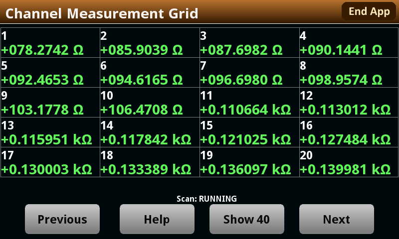
The design files can be found in the Github repository.