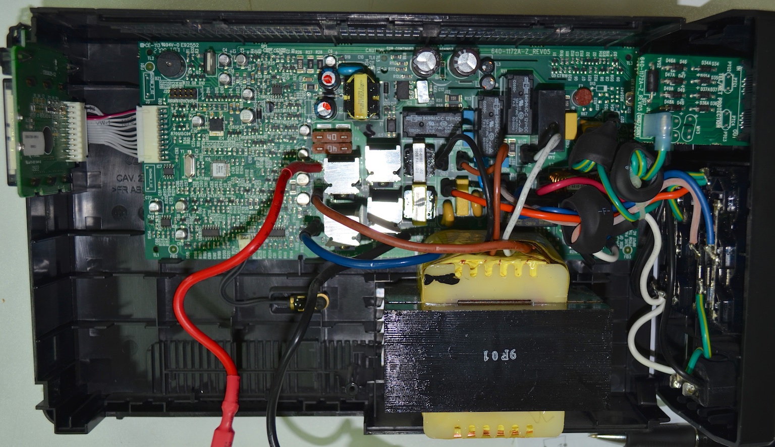
In a previous post I showed pictures of an MGE UPS, its circuit schematic and waveforms of its operation. Since I also have an APC UPS of the same era and of equivalent power range, in this post, the same pictures and waveforms will be shown for this one in order to compare the two of them. To begin, the following pictures shows the full UPS. On the top left, the user screen and buttons are connected to the main board. The battery is housed on the bottom left and on the bottom right the huge 50 Hz multiple winding transformer is shown.
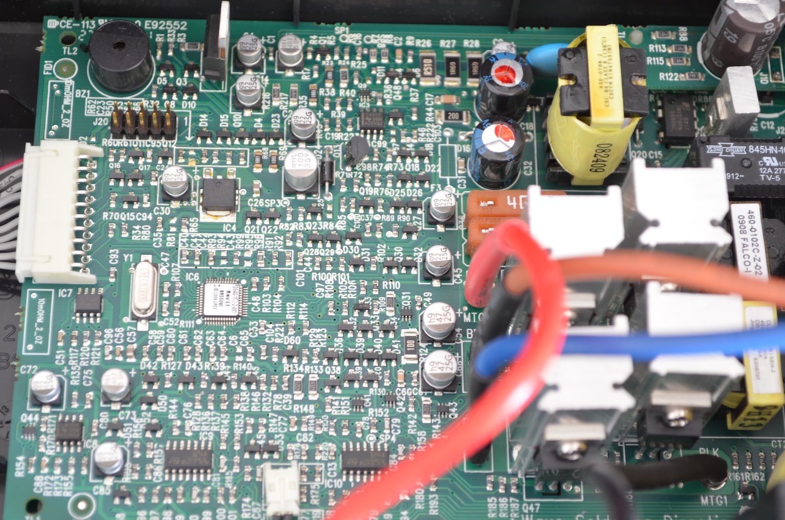
The majority of the UPS components on the control board are SMDs. The board houses the power components on the right. Each inverter transistor has its heatsink. Two 40A fuses can be seen, connecter in series to the battery. The filter inductor is shown as well.
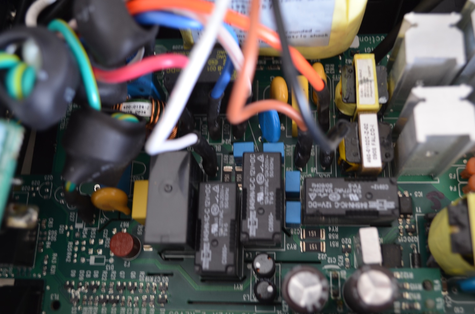
Similarly to the MGE UPS, there are some relays and filters on the power section. Each cable connected to the board has a ferrite heat shrunk on the cable.
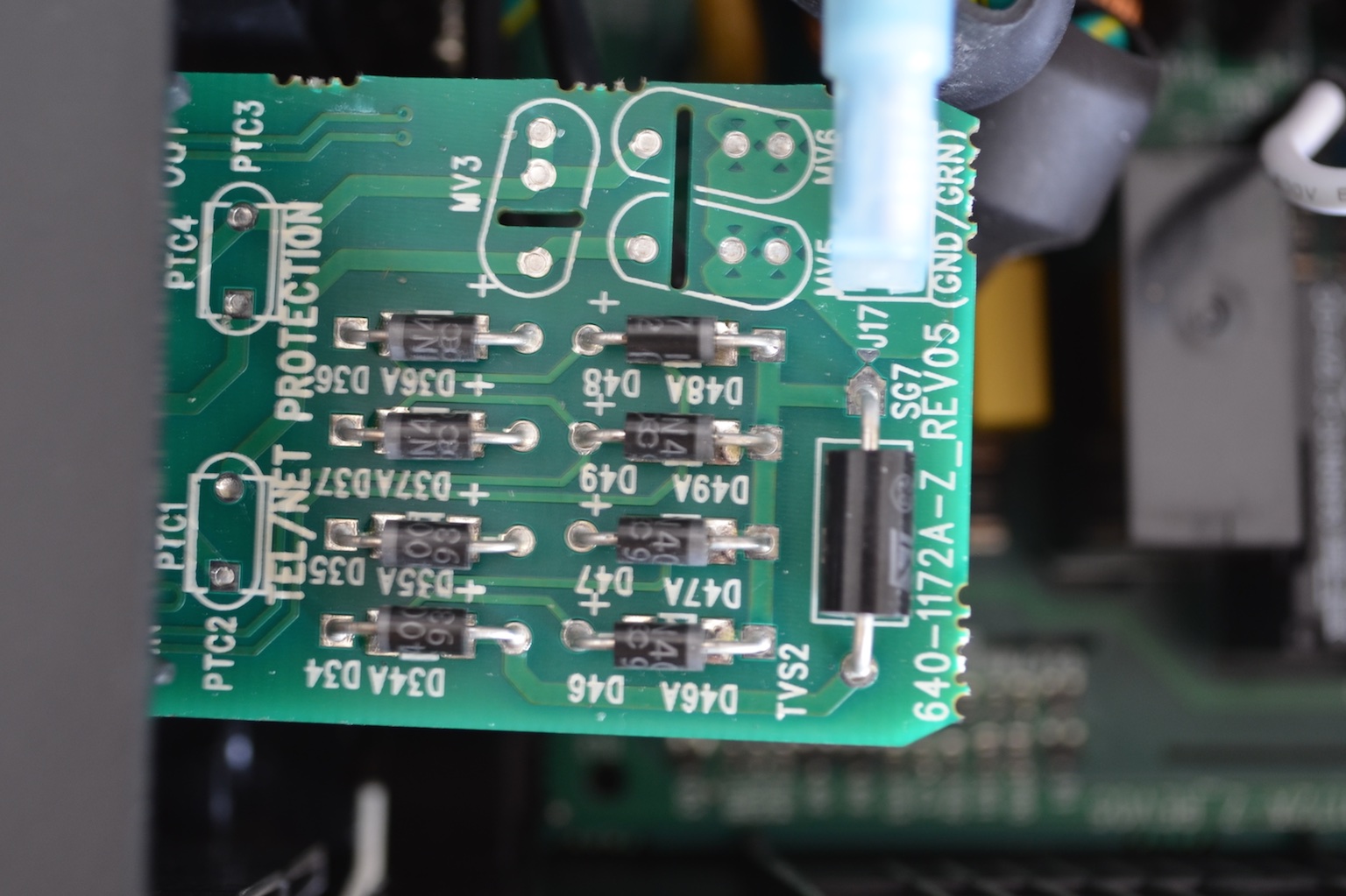
 A separate board is used for the telephone line protection.
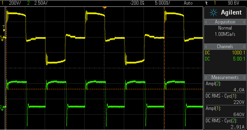
The UPS operation is quite similar. In the following figures the transitions when there is an undervoltage is shown.

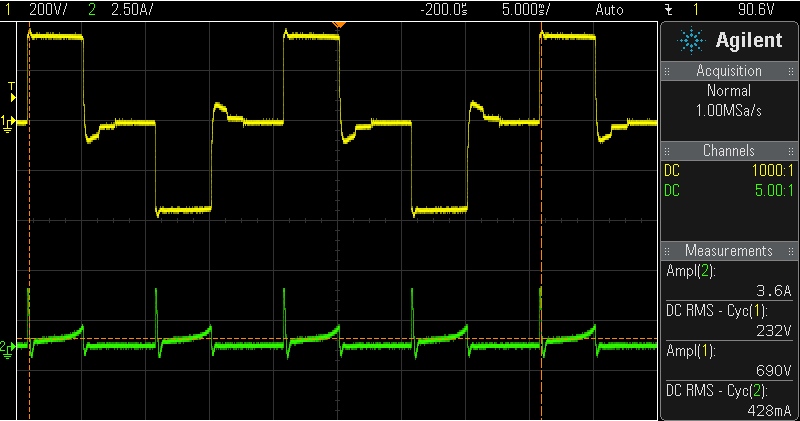
The transition from grid supply to battery supply is shown in the following figures. The battery peak currents during transitions are smaller (about half) compared to the MGE UPS.
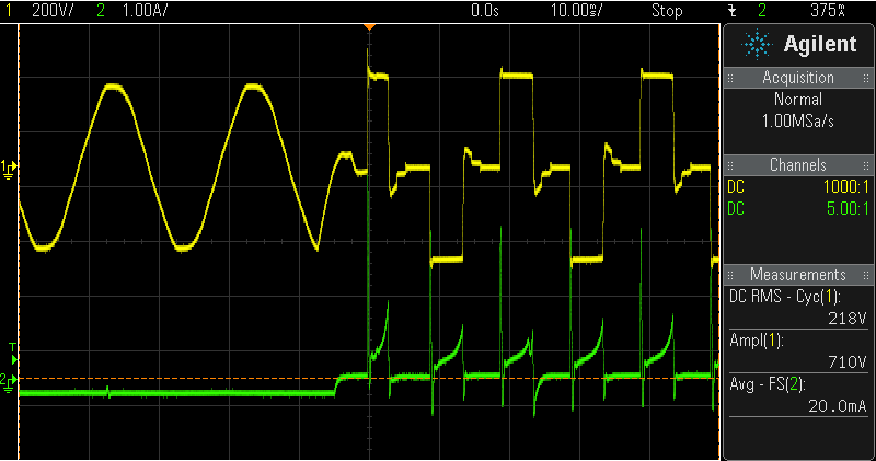
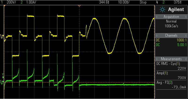
Even if the power circuit seams to be similar, because of the different transformer, a small overshoot is observed during the inverter transistor switch off.
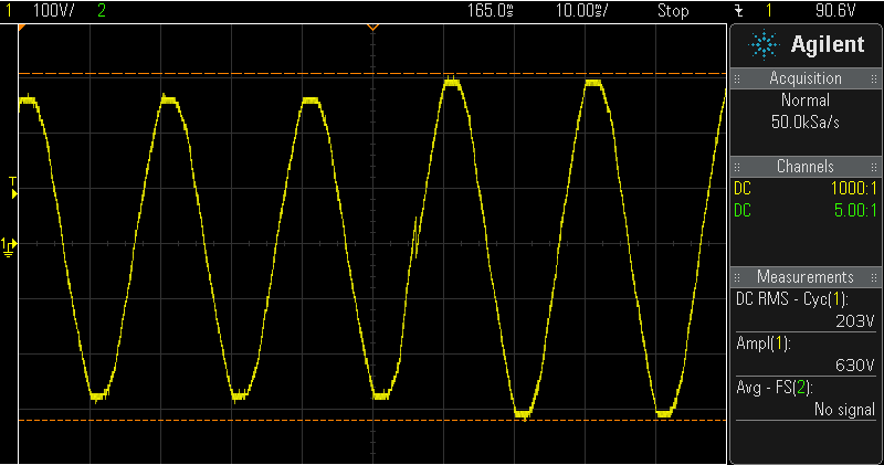
Finally, the output waveform does seem to change, even if the UPS is loaded. For the same load, the MGE UPS had a very different waveform.