I wanted to add some exterior lights using the existing wiring, which would operate during the night. The most common way is to install a programmable timer switch before the lights, which is a hardware or software timer and a relay. However this needs to be installed indoors (unacceptable for my case) or outdoor, on a waterproof enclosure, which however can not be easily programmable.
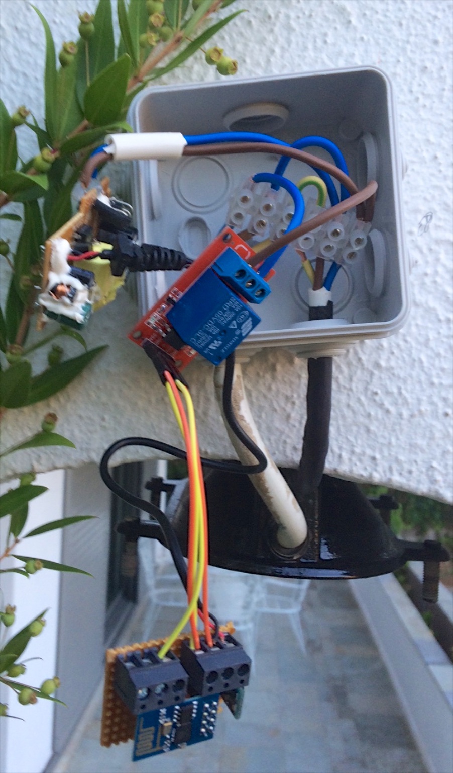
So, instead, I used some simple components to create a switch using a relay. The switch is connected to the home WiFi, so it can be operated using any other client connected on the same network, or via the internet, if enabled. The circuit is housed in a IP55 junction box, near each light.
The main component of the circuit is the ESP8266 WiFi module, which includes a microcontroller and a TCP/IP stack. The ESP8266 needs a 3.3V supply, which is provided by the ac grid. Finally, a GPIO port operates a high voltage relay which connects the light. The following figure shows the complete circuit schematic.
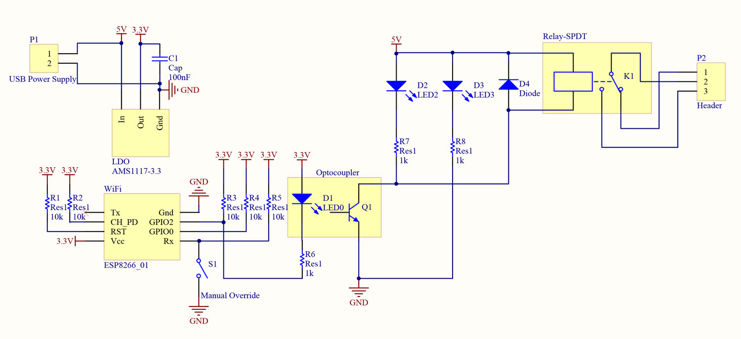
To provide the 3.3V, a USB power supply is used, together with a 3.3V LDO. The AMS1117 regulator needs to provide at least 9mA to operate correctly, so a resistive load needs to be added, together with bypass capacitors and a protection diode. For the current project, an external regulator board was used, which has all the necessary components. A supplemental 100nF capacitor is connected, since during transmission, the ESP8266 demands up to 250mA.
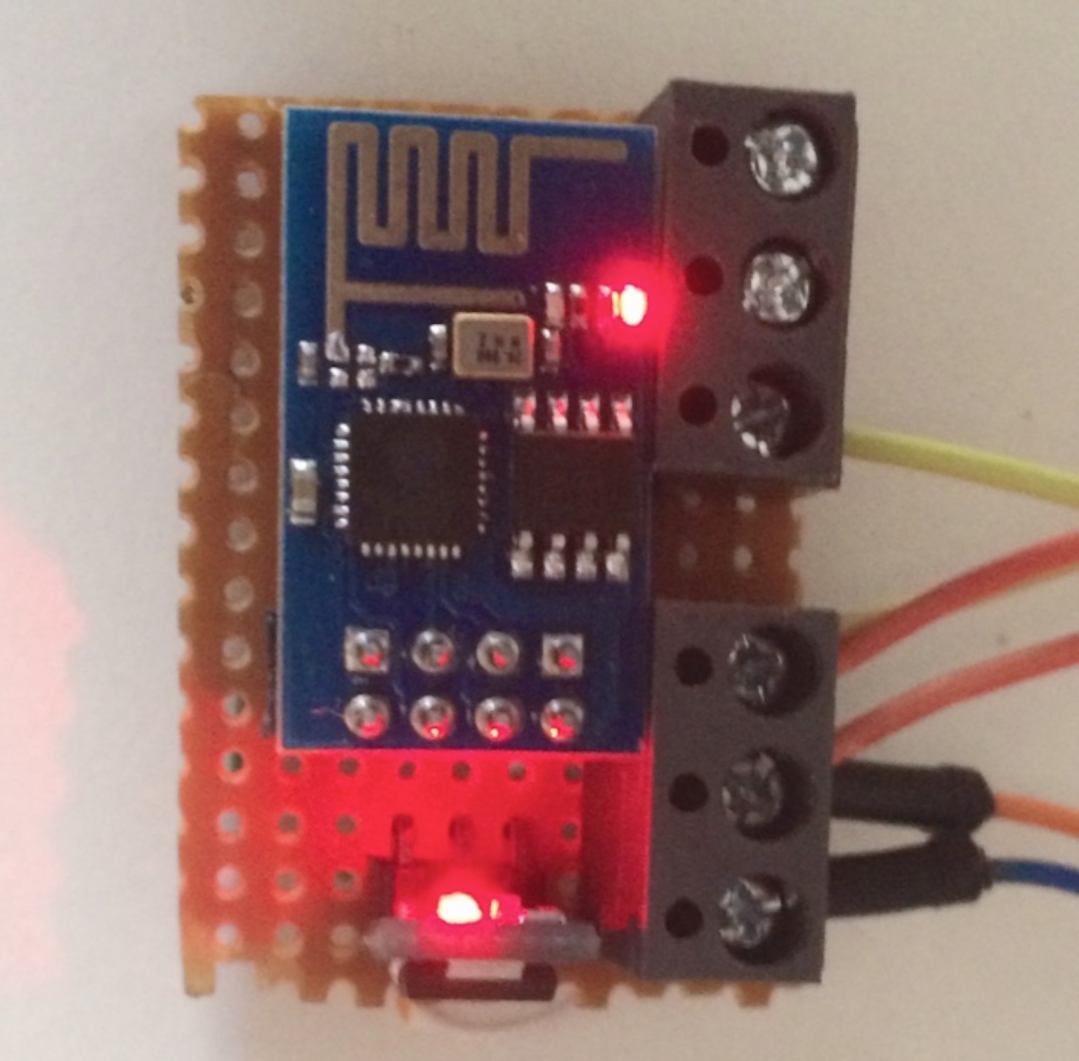
The ESP8266-01 module is used. The ESP8266 has many variants. Different boards, provide different ports. The ESP8266-01 board has the least amount of ports, two GPIOs and the UART peripheral Tx/Rx. For normal operation, during power-up, the GPIO2 needs to be high. The UART peripheral is not used during operation. So, Tx is not connected and Rx has a pull-up resistor, to not be affected by noise. The R3 resistor pulls GPIO2 to Vcc (although D1 does the same job by the manner it is connected). CH_PD enables the module, and needs to be pulled high. RST resets the module when low, so it is pulled to Vcc via R1. GPIO2 is used as an output to drive the relay, whereas GPIO0 is used an input to override manually the state, as it is (still) quicker than to connect via the mobile phone.
The light is connected via a high voltage relay (10A - 250V). Although for the current prototype an external relay board is used, it can be easily implemented in the same board, so it is analytically depicted in the circuit schematic. An optocoupler is used in the input, which can isolate the ground of the microcontroller with the ground of the relay. However, this is not necessary, as the relay provides isolation as well. LED3 shows that the relay is powered on, whereas LED2 shows if the relay is activated. The diode D4 is necessary, to dissipate the power of the relay coil. If this diode was not present, an overvoltage would occur during switch off, which could damage the nearby components. Connector P2 is a high current, high voltage connector.
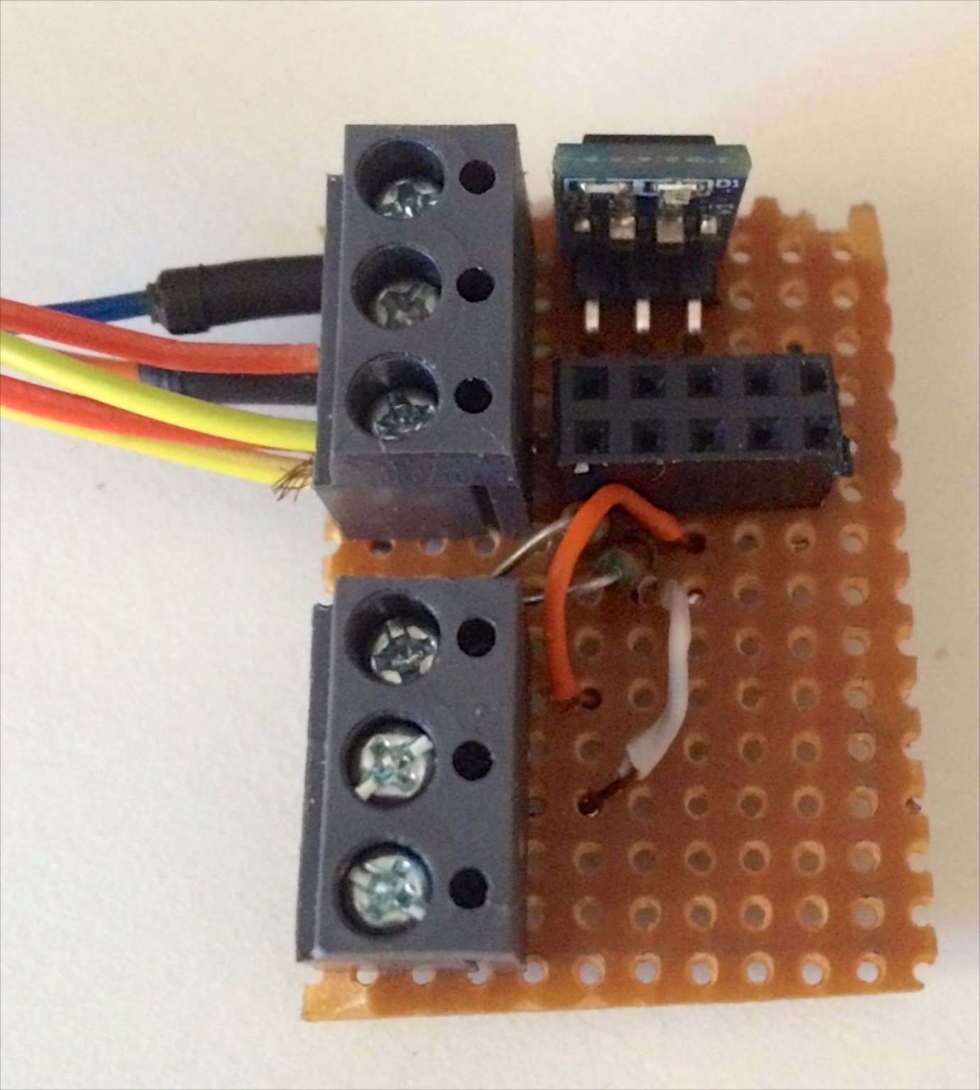
The ESP8266 module, together with the regulator board were installed on a single sided veroboard. A connector is used for the ESP8266 module, in order to remove it for programming.
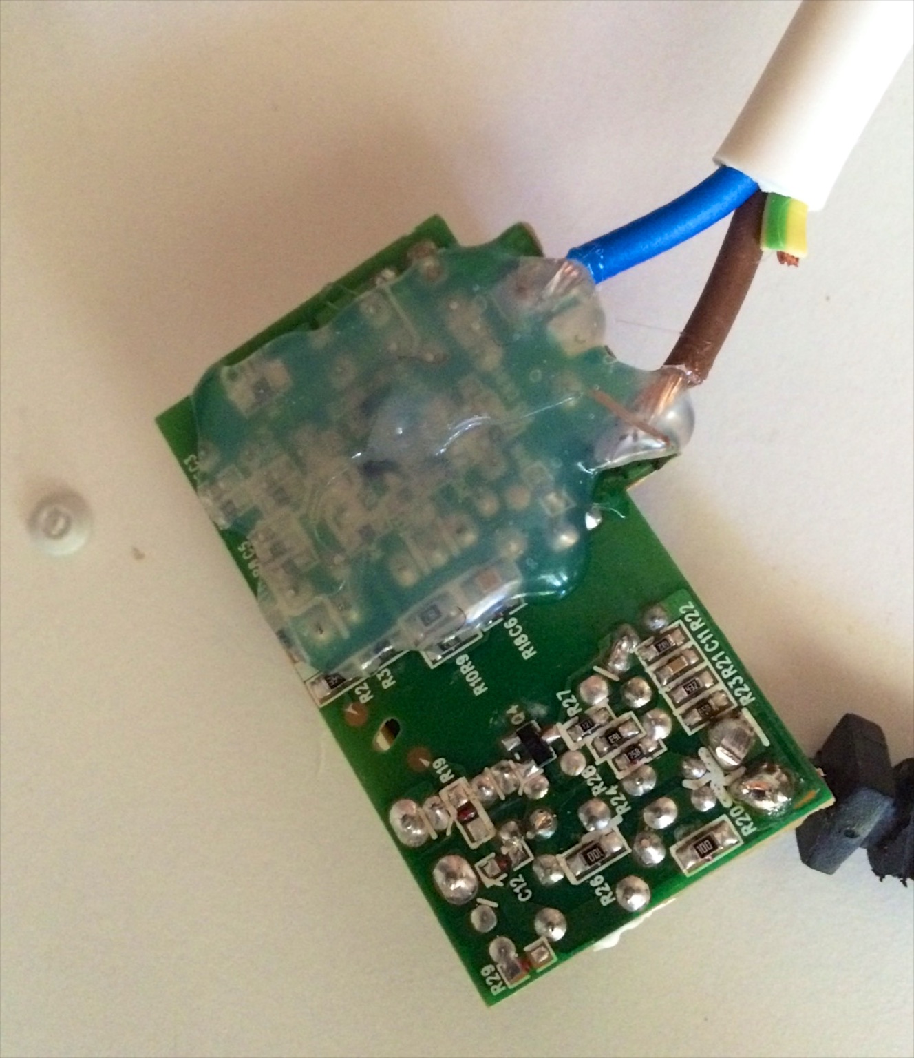
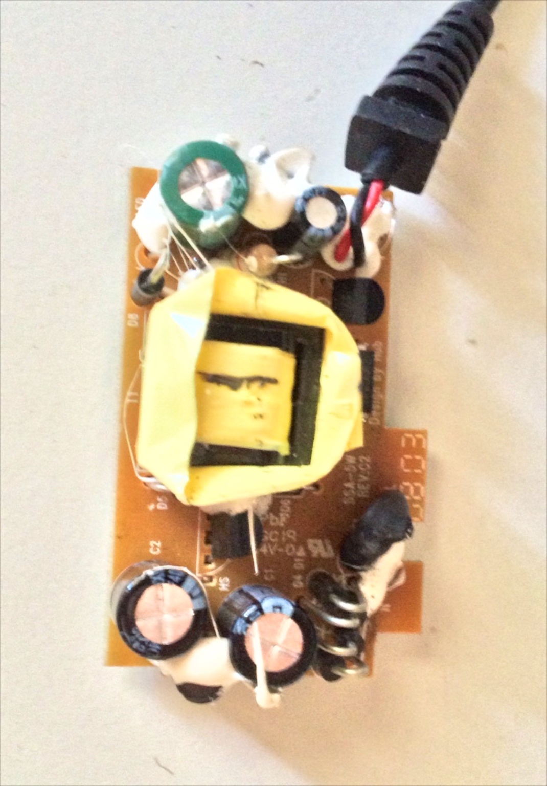
A 5V power supply from an old nokia bluetooth headset is used, which implements a flyback topology. The high voltage circuit (before the flyback transformer) is isolated with hot glue, to ensure that there will be no short circuiting when installed inside the enclosure.
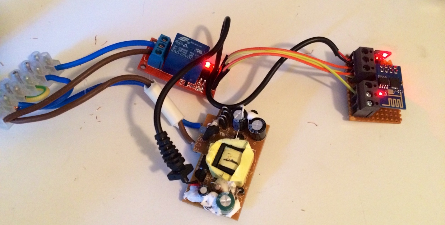
In this photo, the whole circuit is depicted. Power comes from the connector strip shown on the left. The neutral and ground are bridged to the light, whereas the phase passes through the relay. The 5V supply is powered by the phase and the neutral which powers the ESP8266 board through the LDO. The ESP8266 board provides power to the relay board, as well as the signal to switch on the relay.
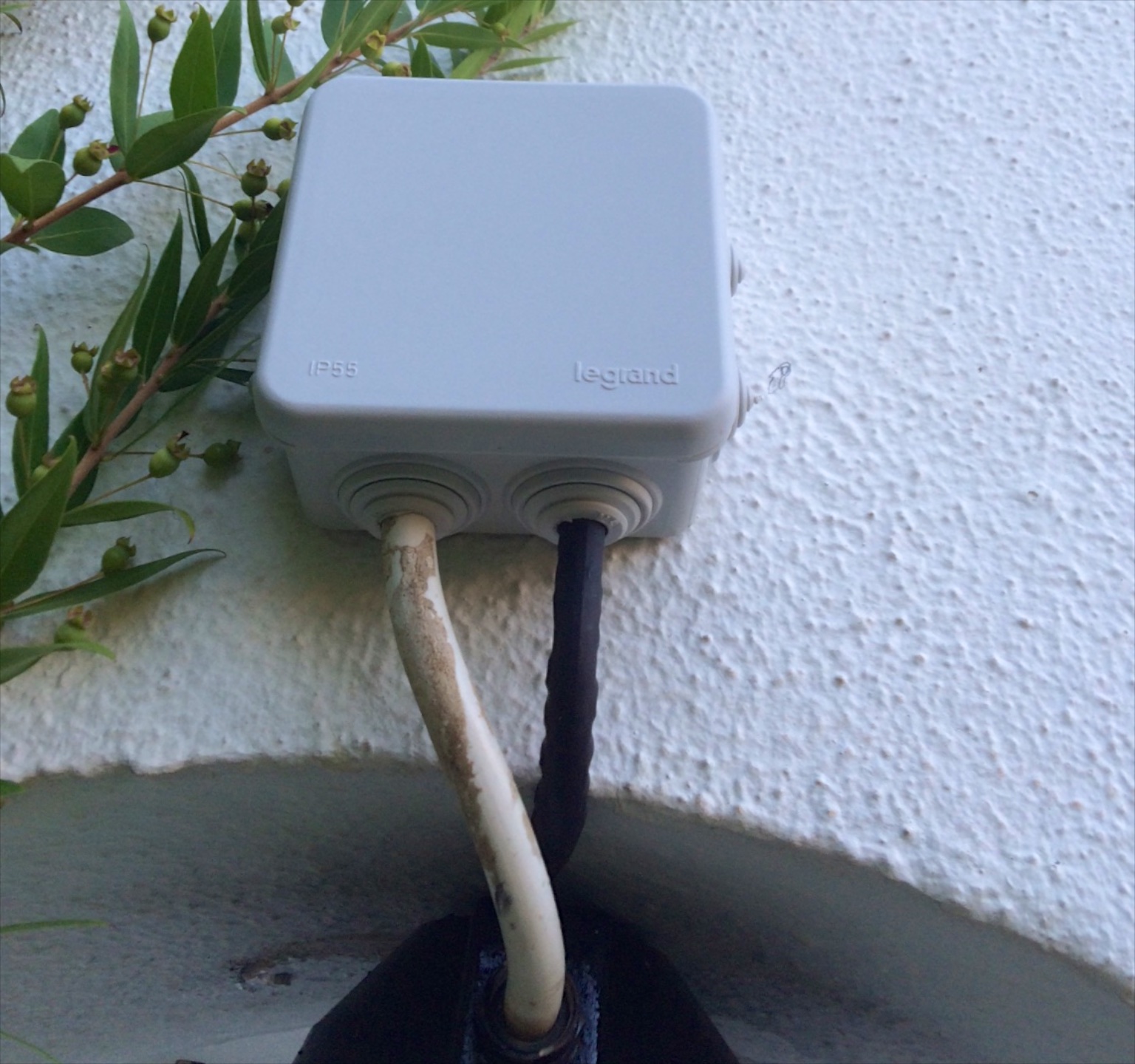
Finally, the installation is shown. A 8cm x 8cm waterproof (IP55) was used, although with careful wiring, the components could fit in a smaller enclosure. The optional manual override switch was not installed in this light box, as the installation hight makes it inaccessible to the user.